TP T 15HD 45 and TP T A 45 Twisted Pair Video and Audio Transmitters 68-924-01 Rev.
Precautions Safety Instructions • English This symbol is intended to alert the user of important operating and maintenance (servicing) instructions in the literature provided with the equipment. This symbol is intended to alert the user of the presence of uninsulated dangerous voltage within the product’s enclosure that may present a risk of electric shock. Caution Read Instructions • Read and understand all safety and operating instructions before using the equipment.
安全须知 • 中文 警告 这个符号提示用户该设备用户手册中 有重要的操作和维护说明。 电源 • 该 设 备 只 能 使 用 产 品 上 标 明 的 电 源 。 设 备 必须使用有地线的供电系统供电。 第三条线 (地线)是安全设施,不能不用或跳过。 这个符号警告用户该设备机壳内有暴 拔掉电源 • 为安全地从设备拔掉电源,请拔掉所有设备后 或桌面电源的电源线,或任何接到市电系统的电源线。 露的危险电压,有触电危险。 电源线保护 • 妥善布线, 避免被踩踏,或重物挤压。 注意 阅读说明书 • 用 户 使 用 该 设 备 前 必 须 阅 读 并 理 解所有安全和使用说明。 保存说明书 • 用户应保存安全说明书以备将来使 用。 遵守警告 • 用户应遵守产品和用户指南上的所有安 全和操作说明。 维护 • 所有维修必须由认证的维修人员进行。 设备内部 没有用户可以更换的零件。为避免出现触电危险不要自 己试图打开设备盖子维修该设备。 通风孔 • 有些设备机壳上有通风槽或孔,它们是用来防止 机内敏感元件过热。 不要用任何东西挡住通风孔。 锂电池 • 不正确的更换电池会有爆炸的危险。 必须使用 与厂家推荐的相同
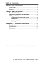
Table of Contents Chapter One • Introduction ........................................................ 1 Introduction . ................................................................................ 1-2 Features ......................................................................................... 1-3 Chapter Two • Installation .......................................................... 1 Rear Panel Connectors ..............................................................
Table of Contents, cont’d TOC-ii TP T 15HD 45 and TP T A 45 • Table of Contents
TP T 15HD 45 and TP T A 45 1 Chapter One Introduction Features
Introduction Introduction The Extron TP T 15HD 45 twisted pair transmitter and the matching TP T A 45 audio input module provide a system for sending RGBHV, RGBS, RGsB, component, composite, or S-video and stereo audio signals over an Extron Skew-Free™ A/V UTP or CAT 5/5e/6 UTP cable to a compatible TP or VTR receiver. An external 12 VDC power supply provides power to both the TP T 15HD 45 and the TP T A 45. The TP T A 45 inputs unbalanced audio through a 3.
* VTR001 is not compatible with component, composite, or S-video. N It is possible to exceed the recommended distances, however, image quality may be reduced. Features • 45 mm opening compatibility — The TP T 15HD 45 and TP T A 45 are designed to fit into a 45 mm mounting frame that is popular throughout Europe. The plate may be wall-mounted or floor box-mounted.
Introduction, cont’d 1-4 TP T 15HD 45 and TP T A 45 • Introduction
TP T 15HD 45 and TP T A 45 2 Chapter Two Installation Rear Panel Connectors Front Panel Connectors and Indicators Cabling and Setup
Installation Rear Panel Connectors TP T A 45 TP T 15HD 45 OUTPUT 1 2 3 4 5 6 7 8 12 VDC .5A MAX. 1a AUDIO AUDIO 1b 4 2 3 TP T 15HD 45 AUDIO AUDIO 12 VDC .5A MAX. TP T A 45 Figure 2-1 — Rear panel views Ä Power input captive screwWiring.eps connector — Connect the included Power 12 VDC external power supply to the 2-pole female direct insertion captive screw connector. N The TP T 15HD 45 and the TP T A 45 share a single power supply. Neither can be remotely powered by the attached receiver.
Å Captive screw digital audio input connector — Connect the digital audio input cables from the TP T A 45 (if installed) to the 2-pole female direct insertion captive screw connector. + AUDIO + - AUDIO - Digital Audio Input Captive Screw Direct Insertion Connector W N b Remove power before wiring. The wire gauge should be 14 - 22 AWG and the maximum distance betwee the modules should not exceed 25 feet.
Installation N Strip approximately 0.43 inch (1.1 cm) of insulation from each individual wire on one end of a TP cable. 12345678 1&2 7&8 3&6 4&5 Twisted Wire Pairs c Power input captive screw connector — Connect power input cables to the 2-pole female direct insertion captive screw connector. + 12 VDC .5A MAX. - Power Input Captive Screw Direct Insertion Connector W d Remove power before wiring.
Front Panel Connectors and Indicators 1 1 COMPUTER AUDIO 3 2 INPUT INPUT TP T 15HD 45 TP T A 45 Figure 2-2 — Front panel views a b Power LED indicator — The LED lights green whenever power is applied. 10 5 1 6 15-pin HD video input connector — Connect computer video input to this connector. N 15 11 Female Input only sync signals, no video signals, on the sync pins, 13 and 14.
Installation, cont’d Cabling and Setup To install the TP T 15HD 45 and TP T A 45 models, follow these steps: a b Turn all of the equipment off and, if applicable, disconnect it from the power source. Connect the TP T 15HD 45 and its receiver to either end of the UTP cable. See Cable testing and Skew delay problems in this chapter. N c d e f g h Connect the external power supply to the TP T 15HD 45 and TP T A 45 (if installed). See Rear Panel Connectors in this chapter.
• TPX 88A As a stand-alone transmitter, the TP T 15HD 45 is compatible with: • VTR001, VTR001 AAP, and VTR001 MAAP (RGBHV/ RGBS only) • TPX 88 Cable testing To ensure proper cable termination, each transmission cable system that uses CAT 5e or CAT 6 cable should be tested (Extron Skew-Free cable does not need to be tested). Testing the cable from the transmitter and receiver gives the most accurate indications of cable problems.
Installation, cont’d • Switch to Extron Skew-Free cable. • Add a skew compensation cable equal to the length of pair skew to the receiver’s output. • Install an SEQ 100 15HD Skew Equalizer on the video output of the receiver and adjust the skew for the leading video image. Mounting The TP T 15HD 45 and TP T A 45 are designed to fit into a wallmountable or floor box-mountable 45 mm mounting frame.
TP T 15HD 45 and TP T A 45 A Appendix A Reference Information Specifications Parts Lists
Reference Information Specifications Video— video models Number/signal type ��������������������� 1, 2, or 4 sets of proprietary analog signals Connectors TP T 15HD 45 ��������������������� (1) 8-pin spring force captive wire connector All other models ���������������� 1, 2, or 4 shielded RJ-45 female Video input— video models Number/signal type TP T 15HD A, TP T 15HD 45 1 analog RGBHV, RGBS, RGsB, component video, or S-video; or 1 S-video and 1 NTSC/PAL/SECAM composite video from a single source; or 3 NTS
Nominal level �������������������������������� 1 Vp-p for Y of component video and S-video, and for composite video 0.7 Vp-p for RGB and for R-Y and B-Y of component video 0.3 Vp-p for C of S-video Minimum/maximum levels �������� 0.3 V to 1.
Reference Information, cont’d Maximum level ������������������������������ +5.5 dBu, (unbalanced) at 1%THD+N CMRR ���������������������������������������������� >75 dB @ 20 Hz to 20 kHz N 0 dBu = 0.775 Vrms, 0 dBV = 1 Vrms, 0 dBV ≈ 2 dBu Audio output — refer to the TP Receivers Family User’s Manual, part #68-547-02. General Recommended cable type ������������ Enhanced Skew-Free™ A/V UTP Cable or CAT 5/5E/6 (shielded or unshielded) Power TP T 15HD A, TP T 15HD AV 15 VDC, 0.
Enclosure type ������������������������������� Metal Enclosure dimensions TP T 15 HD A, TP T 15 HD AV, TP T BNC DA4 1.3" H x 6.8" W x 4.5" D (<1U high,
Reference Information A-6 TP T 15HD 45 and TP T A 45 • Reference Information
Included Parts These items are included in each order for an IR 102 Remote Kit (part #70-224-01): Included parts Replacement part number IR 102 Rx Remote Receiver IR 102 Handheld Remote Control 70-224-10 12 VDC, 1 A external power supply kit 70-055-01 IR sensor on a 6-foot cable RS-232 male-to-female cable, 6 feet (1.8 m) 26-433-03 IEC power cord Tweeker (small screwdriver) Hook-and-loop fasteners 3.5 mm, 2-pole captive screw connector 10-319-15 3.
Reference Information A-8 TP T 15HD 45 and TP T A 45 • Reference Information
Extron Warranty Extron Electronics warrants this product against defects in materials and workmanship for a period of three years from the date of purchase.
Extron USA - West Headquarters +800.633.9876 Inside USA / Canada Only +1.714.491.1500 +1.714.491.1517 FAX Extron USA - East Extron Europe Extron Asia Extron Japan Extron China Extron Middle East +800.633.9876 +800.3987.6673 +800.7339.8766 +81.3.3511.7655 +81.3.3511.7656 FAX +400.883.1568 +971.4.2991800 +971.4.2991880 FAX +1.919.863.1794 +1.919.863.1797 FAX +31.33.453.4040 +31.33.453.4050 FAX +65.6383.4400 +65.6383.