
Setup guide

TLP 350CV Setup Guide
68-1692-50 Rev. A
12 09
The Extron TouchLink
™
3.5 inch Cable Cubby
®
TLP 350CV
provide users with access to AV connectivity using convenient
pullout cables. It also provides simple and versatile
configuration and control for a range of IP Link
®
control
systems. With a required IP Link controller, the touchpanel and
10 customizable buttons provide control of an AV system and
room environment. On-screen graphic and text objects allow
users to activate or regulate system control functions.
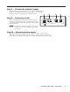
The TLP 350CV communicates with the configurable IP Link controller via an Ethernet connection. Two BNC
connectors allow the screen to be used to preview composite video or S-video.
N
The RJ-45 output on the rear panel of the TLP 350CV must be connected to a network switch, hub, or router that
is connected to an Ethernet LAN or the Internet. An Extron IP Link controller must also be connected to the same
network. Suggested models include:
• IPL T S series • IPL T CR 48
• IPL 250 • IPL T SFI 244
This guide provides basic instructions for an experienced installer to mount and perform initial configuration on
the TLP 350CV. When possible in the following pages, line drawings are used to clarify steps discussed in the text.
Where appropriate, images have one or more numbers corresponding to a specific step described.
Visit the TouchLink™ panel site at www.extron.com/touchlink for assistance in the setup and operation of the
TLP 350CV, or to enroll in online training. For additional assistance with the touchlink panels, call 1.800.633.9877.
Installation Overview
Install and set up the TLP 350CV enclosure as follows:
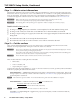
c Verify the surface cutout dimensions of the TLP 350CV "Step 1 — Obtain cutout dimensions" on page 2.
To obtain the most recent cutout dimensions, visit the Extron Web site at www.extron.com.
c If planning to use a routing template that has not been prepared, prepare the template. Refer to the
TLP 350CV User’s Manual, available on the included DVD or the Extron Web site, www.extron.com.
c Cut a hole in the surface where the enclosure will be installed. See "Step 2 — Cut the surface" on page 2. Use
one of the following as a guide:
• The optional metal routing template
• The cut-out dimensions, programmed into a CNC wood router
• A paper surface cut-out template
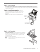
c Run all cables necessary to support the AC connector, the cables stored in the cubby, and all planned AAP
connectors. See "Step 3 — Run all cables" on page 3. Leave enough slack in the cables to connect or route them
before the cubby is installed in the table.
c Install the power module. If the location requires electrical conduit, install an Extron flexible conduit kit. Refer
to the Flexible Conduit Kit Installation Instructions, Extron part #68-734-01 available at www.extron.com. See
"Step 4 — Install power module" on page 3.
c Install cables into the cable pass-through AAPs and loosely fasten to the AAP Shelf. If applicable, install
passive AAPs and loosely fasten to the AAP shelf. Connect cables to the rear connectors.
See "Step 5 — AAP assembly" on page 3.
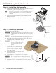
c Install the AAP shelf assembly into the Cable Cubby. See "Step 6 — Install the AAP assembly" on page 4.
c Mount the TLP 350CV in the table. See "Step 7 — Mount the enclosure" on page 4
c Connect the external power supply. See "Step 8 — Connect the external supply" on page 5.
c Connect a LAN cable. See "Step 9 — Connect to a LAN" on page 5.
c If using the video monitoring capabilities of the TLP 350CV, make video input connections. See "Step 10 —
Connect preview inputs" on page 5.
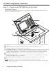
c Apply power. See "Step 11 — Power on the TLP 350CV for the first time" on page 6".