
Setup Guide User guide


6
TLP 710CV and TLE 710 • Setup Guide (Continued)
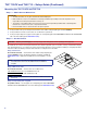
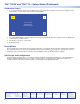
Step 12 — Power on the TLP 710CV for the First Time
Power on all the devices connected to the TLP710CV.
When the 12 VDC power supply or the PoE power
supply is switched on, the TLP 710CV will boot up and,
if a graphical user interface (GUI) has been designed
and loaded onto the touchpanel, that screen will be
displayed. If a GUI has not been loaded, a plain blue
screen will be displayed.
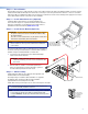
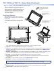
Front Panel Features
With the lid down, the screen, light sensor, and the
illumination LED are disabled. They are all activated by
opening the lid.
To see all the front panel features, remove the bezel,
using the Extron Removal Tool (see the gure to the
right).
4
1
3
5
2
6
7
For a complete description of all these features and their function, see the TLP 710CV User Guide.
a
Light Sensor — monitors ambient light level and adjusts screen brightness.
b
LCD screen — has a 800x480 resolution with a touch overlay. Extron software is used to design and congure a graphic user
interface to display buttons, text, or icons, which have user-dened functions associated with them (see GUI Design and
Conguration on page 8).
c
MTP Video Signal Adjustments — Three MTP signal adjustments are available for S-video: luminance gain (VID/Y), S-video
chrominance gain (C), and sharpness (S). For composite video signals, the VID/Y adjustment controls the gain.
d
Reset LED — provides feedback about the mode status when the user presses the reset button.
e
Controller Communication LED — is unlit during normal operation. The LED blinks red if the connection to the IP Link
controller is lost.
f
Reset Button — allows the unit to be reset to one of four different modes (see page 8).
g
Menu Button — activates the on-screen menus for calibrating the unit.
NOTE: The MTP video signal adjustments, reset LED, controller communication LED, reset button, and menu button
can be accessed only after removing the front panel bezel (see the figure at the top of the page).
h
Speaker — provides audible feedback for the user.
i
Bezel Removal Slots — allow removal of bezel, using Extron removal tool (see the gure at the top of the page).
j
Illumination LED — provides light for cable cubby enclosure.
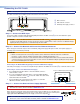
9
10
8
Extron
Extron
Insert the removal tool in the
slot at one top corner and
loosen the bezel away from
the screen.
Move the removal tool to
the second slot and
loosen the bezel away fr
om
the screen.
Slide the removal tool along
one side until the bezel
separates from the unit.