
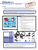
Setup Guide User guide


4
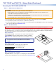
TLP 710CV and TLE 710 • Setup Guide (Continued)
4
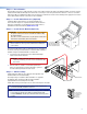
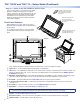
Step 7 — Install the AAP Assembly
1. From under the table, push the rst AAP assembly
through the bottom of the enclosure. The holes in the
rear bracket must align with the bottom row of holes on
the rear face of the enclosure.
TIP: Ensure there is enough space above the
AAP assembly for the lid to close completely
without cables or connectors contacting the
touchpanel.
2. Secure the AAP assembly into position with the
provided Phillips head screws.
3. Tighten the nuts that secure the AAPs to the brackets.
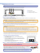
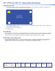
Step 8 — Mounting the Enclosure
Mount the Cable Cubby enclosure in the table.
CAUTION: The anged edges of the trim ring are sharp. Exercise caution when the cubby is not installed in a table to
prevent personal injury.
ATTENTION: The trim ring edges are soft and can easily be nicked or bent. Exercise caution when handling and mounting
the enclosure.
1. Remove the edge grommet protecting the edges of the trim ring and the plastic lm on the nished surfaces.
ATTENTION: Do not use isopropyl alcohol or other solvents to clean the Cable Cubby. Strong solvents will ruin some
nishes.
2. Carefully lower the enclosure into the hole cut in the table (see
“Step2 — Cut the Surface” on page 2). Ensure the trimring(
e
) is
ush with the top of the table.
3. Under the table, attach the table clamps (
c
) to the pins on each side
of the enclosure. It may be necessary to loosen the wingnuts (
a
)
and the Phillips head screws (
b
).
4. When the clamps are properly seated on the pins, tighten the Phillips
head screws until the clamp faces (
d
) are tightly secured against the
bottom of the table.
5. To prevent the screws from becoming loose, secure the wingnuts
against the table clamp bodies.
1
4
5
3
2
COMPUTER
AUDIO
Phillips Head Screws
(secure AAP
Assembly)
Tighten down
AAP Nuts.
Push assembly through
bottom of enclosure.
Large slot
provides tool
access to fasten
rear brackets.
b
a
c