
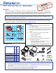
Setup Guide User guide


3
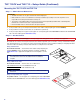
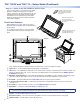
Step 3 — Run all Cables
Run all cables necessary to support the AC connector, the cables stored in the cubby, and all planned AAP connectors. Run the
cables below the table and through the hole that was cut in Step 2. Leave enough slack in the cables to connect or route them
before the cubby is installed in the table. Leave enough space under the enclosure for the external power supply and connection
of AV cables and the network connection for the TLP710CV.
Step 4 — Install Cable Retractors (Optional)
If required, Extron cable retractors should be installed in the
enclosure at this stage. For complete information about retractors
and how to install them, see the Retractors User Guide, which is
available from the Extron website (www.extron.com).
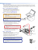
Step 5 — Install Power Module (Optional)
ATTENTION: For units that are used in North America, only use
AC power modules that are UL Listed Model “Cable Cubby
AC Power Module”.
The unit is not UL Listed if it uses any AC power module other
than Model “Cable Cubby AC Power Module”.
NOTE: For models that do not include a power module, see the
Extron website to select a power module that is suitable for
your location.
The power module takes up two or three AAP spaces, depending on
the model, and may be installed before or after the AAP assembly is
installed. It may be installed with AAPs on either side.
1. Secure the power module into position with #4-40 Phillips
head screws and star washers.
CAUTION: Risk of electric shock: To ensure good
electrical grounding, you must use the star washers with
the screws.
2. Run the cable or conduit to a convenient junction box.
Extron recommends the circuit be attached to a junction
box that is directly wired to the main circuit.
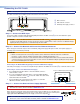
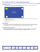
Step 6 — AAP Assembly
Install all desired cables into the cable pass-through AAPs and
install the AAPs into the Cable Cubby.
The simplest way to install the cables and AAPs is to populate
the AAP brackets outside the cubby and then install the
populated AAP shelf assembly into the cubby.
Install cables in the pass-through holes as shown in the gure to the right.
TIP: Hand tightening the #4-40 nuts makes it easier to place and
secure the assembly inside the enclosure.
NOTE: An extra column of AAP bracket mounting points is available
for use with TLP Single-space AAP mounting brackets (part
number 70-693-01). Single-space brackets will not fit in any other
location.
Secure the power module
to the TLP 710CV frame
with #4-40 Phillips head
screws and star washers.
Rear Brackets
Front Brackets
The extra column
of mounting points
is for installing
single-space
AAP brackets.