
User Guide Manual

SIS
™
Programming and Control, cont’d
System 5 IP • SIS
™
Programming and Control5-36
PRELIMINARY
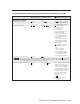
Command/response table for special function SIS commands, continued
Command ASCII Command Response
X?
values
(host to MLC) (MLC to host) and additional descriptions
PC
DOC
CAM
VCR
PIC
MUTE
F 1
F 2
ON OFF
MENU NEXT
AUTO
IMAGE
F3
DVD
LAPTOP
MAX
MID
VOLUME
ADJUST
MIN
23 4
5/ PC
DISPLAY
1
INPUT SELECTION
SCP 150
INPUT
1
INPUT
2
INPUT
3
INPUT
4
INPUT
5
PROJECTOR
ON
PROJECTOR
OFF
FUNCTION
BUTTON 4
DISPLAY
PIC
MUTE
IR
AUTO
IMAGE
VOLUME
25 241 2
1 2 8
5
6
7
5 6
21
4
121
123
7
3
6
5
111
109
125
110
116
118
24
120
122
124
113
112
114
119
117
115
25
108
7 9 10 11 12 13
9 10 11 12 13
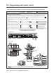
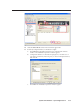
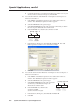
System 5 IP with FPC
Button/Switch Memory Block Numbering for the
System 5 IP Switcher, SCP 150, and IR 402
SCP 150
IR 402
Clockwise
(up)
Counter-
Clockwise
(down)
25 24
Clock-
wise
Counter-
clockwise
See System 5 IP
front panel.
9-22
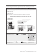
Button press/release emulation
Emulating a button press or release causes the commands and actions that are associated with the button via the main
event script to be executed. Button emulation triggers only what has been set up via the Button Config. part of the
Windows-based configuration program. Emulation does not trigger the built-in SIS input switching commands (
X200
!)
or the projector power on/off commands (1P or 0P).
See the diagrams below and on the next page to determine the number of the memory block associated with each
button.
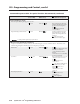
Emulate a button/switch press
X?
*42 # SwPrs*
X?
X?
= the number of the memory
block for the button/switch for
which you want to emulate a
press (1 - 127). See diagrams.
Emulate a button/switch release
X?
*43 # SwRls*
X?
X?
= the button’s/switch’s
memory block number.
Emulate a button press-and-release
X?
*44 # SwCmd*
X?
X?
= the button’s/switch’s
memory block number.
The input button register numbering shown above is for a stand-alone System 5 IP switcher. For a System 5 IP with a
slaved MPS 112 switcher, the input button register assignments differ.