
User Guide Manual

5-13System 5 IP • SIS
™
Programming and Control
PRELIMINARY
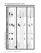
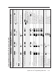
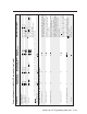
Relay functions
Force relay on
X1
*1O
X1
%2A1O Rly
X1
* 1 Turn relay number
X1
on.
Force relay off
X1
*0O
X1
%2A0O Rly
X1
* 0 Turn relay number
X1
off.
Toggle relay
X1
*2O
X1
%2A2O Rly
X1
*
X5
Toggle relay
X1
on/off.
X5
= 1 (on) or 0 (off).
Pulse relay
X1
*3*
X63
O
X1
%2A3%2A
X63
O Rly
X1
*
X5
Set a specific (
X1
) relay’s pulse time (
X63
) in
Rly
X1
*
X5
20 ms increments from 20 ms (minimum) to
65535 ms (maximum).
Default pulse length = 500 ms.
There will be two responses from the unit because the relay is pulsed. The configuration software will force the relay to turn off before pulsing.
View the relay state
X1
O
X1
O
X5
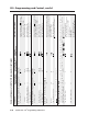
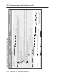
Front panel security lockout modes (executive modes)
Disable lockout modes
24
0X 0X Exe 0 Default setting. Adjustments & selections
can be made from the front panel in addition
to via RS-232, Telnet, or Web browser.
Enable lockout mode 1
24
1X 1X Exe 1 Lock menu access on a System 5 IP that has
front panel buttons. Buttons and Volume
knob are unaffected.
Enable lockout mode 2
24
2X 2X Exe 2 Lock menu access and buttons on all models
of System 5 IP. The Volume knob is
unaffected. Only volume adjustment is
available via the front panel. For switchers
without an FPC, the input LED flashes if
you press the input 5 button while this
mode is enabled.
Enable lockout mode 3
24
3X 3X Exe 3 Lock all front panel selections, adjustments,
and menu access. Make selections, changes,
and configure features via RS-232 or Ethernet
only. The whole front panel is locked.
View the lockout mode status X X
X209
Show lockout (executive mode) status.
X209
= the lockout mode (0 through 3, as
explained above).
Example:X 0
Executive mode is off.
Command/response table for SIS commands (continued)
Command ASCII (Telnet) URL Encoded (Web) Response Additional description
(host to switcher) (host to switcher) (switcher to host)