
User Guide Manual

SIS
™
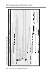
Programming and Control, cont’d
System 5 IP • SIS
™
Programming and Control5-12
PRELIMINARY
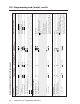
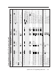
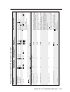
Command/response table for SIS commands (continued)
Command ASCII (Telnet) URL Encoded (Web) Response Additional description
(host to switcher) (host to switcher) (switcher to host)
View power sensor status 8S 8S
X213
If the switcher is connected to an Extron
Power Sensor that monitors the projector/
display, this tells you whether the display is
still powered on.
X213
is as follows:
00 = power sensor is connected and is not
sensing projector power (detector voltage is
low, signal pin voltage is high).
01 = power sensor is connected and sensing
projector power (detector voltage is high).
02 = sensor is disconnected or sensor is
connected but sensitivity is too high (voltage
is low at both the detector and signal pin).
View power sensor signal pin status 9S 9S
X214
Power sensor signal pin status:
00 = voltage is low.
01 = voltage is high.
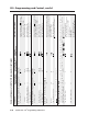
View all voltage & temp. status 11S 11S responses from commands 12S•13S•14S•15S
View all voltages (from main and amplifier
power supplies) and the switcher’s internal
temperature at once.
Example: 11S 11S +11.2•-11.3•+20.0•104
View + main power supply voltage 12S 12S +
X206
Display the operating voltage of the
switcher’s + main power supply.
View - main power supply voltage 13S 13S –
X206
Display the operating voltage of the
switcher’s - main power supply.
View power amp supply voltage 14S 14S +
X206
Display the operating voltage of the
amplifier’s power supply.
View internal temperature status 15S 15S
X207
Display the internal operating temperature
in degrees Fahrenheit.