
User Guide Manual

2-13System 5 IP Switchers • Installation: Labeling, Mounting, Cabling
PRELIMINARY
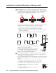
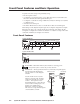
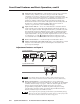
Clip Down
1
1&2
3&6
4&5
7&8
2345678
12345678
RJ-45
connector
Twisted
Pairs
Straight-through Cable
(for connection to a switch, hub, or router)
End 1 End 2
Pin Wire Color Pin Wire Color
1 white-orange 1 white-orange
2 orange 2 orange
3 white-green 3 white-green
4 blue 4 blue
5 white-blue 5 white-blue
6 green 6 green
7 white-brown 7 white-brown
8 brown 8 brown
Crossover Cable
(for direct connection to a PC)
End 1 End 2
Pin Wire Color Pin Wire Color
1 white-orange 1 white-green
2 orange 2 green
3 white-green 3 white-orange
4 blue 4 blue
5 white-blue 5 white-blue
6 green 6 orange
7 white-brown 7 white-brown
8 brown 8 brown
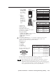
• Use a straight-
through cable
for connection
to a switch,
hub, or router.
• Use a
crossover
cable for
connection
directly to a
PC. Wire the
connector as
shown in the
tables.
Configure the
settings for this
port via either SIS
commands or the Global
Configurator program. See chapters
four and five for details.
LAN port defaults:
• switcher’s IP address: 192.168.254.254
• gateway’s IP address: 0.0.0.0
• subnet mask: 255.255.0.0
• DHCP: off
6
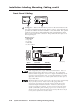
Configuration/RS-232 port — For switcher configuration and control,
connect a Windows-based PC or an RS-232 control system to the
System 5 IP via this female, 9-pin HD connector.
RS-232 protocol:
• 38400 baud
• 1 stop bit
• no parity
• 8 data bits
• no flow control
The pin assignments of this
connector are as follows:
DB9 Pin Locations
Female
51
96
The front panel 2.5 mm mini stereo connector Config port serves the same
function as this rear panel port but is independent from it.
Both configuration ports require 38400 baud communication. This is a
higher speed than many other Extron products use. The System 5 IP
configuration software automatically sets the connection for the appropriate
speed. If using HyperTerminal or a similar application, make sure the PC or
control system connected to these ports is set for 38400 baud.
Pin RS-232 function Description
1 – No connection
2 Tx Transmit data
3 Rx Receive data
4 – No connection
5 Gnd Signal ground
6 – No connection
7 – No connection
8 – No connection
9 – No connection