
User Guide Manual

6-11System 5 IP Switchers • Special Applications
Extron
System 5 IP
System Switcher
Extron
MVC 121
Mixer/Volume
Controller
Wireless
Microphone
System
Hardwired
Microphone
100-240V 1.3A
50-60Hz
21
C
C
43
C
6
5
C
Tx
Rx
G
G
S
G
S
G
S
G
S
G
G
Ps
+V
+V
CM
IR
SCP
R
Y/C
G
Y
B
VH
VID
Y/C
VID
CY
R/VID G/Y B/C
H
V
C
VID
VH
R/VID
G/Y B/C
INPUT 1
INPUT 3
INPUT 4
INPUT 2
R
CM/IR/SCP
RS-232
PROJ CONT
AUDIO
RELAYS
IR/SERIAL OUT
E
C
B
B
D
A
A
L LINEOUT R
L PREAMP R
L 1 R
L 2 R
CONFIG/RS-232
LAN
OUTPUT
A
L 3 R
L 4 R
B
C
D
MVC 121
ON
INPUTS
OUTPUTS
LEVEL
48V
ON
OFF
MAIN 3
LINE
MIC
RS-232
MUTE
Tx Rx
POWER
12V
0.2A MAX
L
1
2
R
3
1
2
3
4
1
2
1
2
MIXER/VOLUME
CONTROLLER
FIXED
L
R
MIC 1
MIC 2
VARIABLE
L
R
CH 003
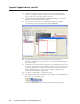
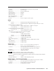
Audio Amplifier2 Program Speakers4 Ceiling Speakers
or
A system featuring a System 5 IP without amplifier, an MVC 121 for
volume control and mixing, and an external amplifier
Slaving an MPS 112 Switcher to a System 5 IP
To allow more inputs, you can slave an Extron MPS 112 or MPS 112 CS switcher to
the System 5 IP. That yields a total of 14 available inputs: 5 RGB, 4 S-video, 4
composite video, and 1 composite or S-video. At this time the MPS 112 Series
models are the only switchers that can be slaved to a System 5 IP.
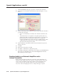
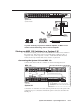
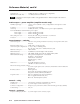
Connecting the System 5 IP and MPS 112
Connect cables between the two switchers as shown in the diagram below.
50/60 Hz
100-240V 0.5A MAX
(VIDEO)
MPS 112
PROG OUT
OUT4321
OUT
OUT
OUT
RS-232
432
2
1
1
2
1
4
3
4
3
L
R
OUT4321
(S-VIDEO)
AUDI O
VIDEO VGA (VGA)
MIC IN
S-VIDEO
100-240V 1.3A
50-60Hz
+
_
LEFT
+
RIGHT
_
21
C
C
43
C
6
5
C
Tx
Rx
G
G
S
G
S
G
S
G
S
G
G
Ps
+V
+V
CM
IR
SCP
R
G
Y
B
VH
VID
VID
CY
R/VID G/Y B/C
H
V
C
VID
VH
R/VID
G/Y B/C
INPUT 1
INPUT 3
INPUT 4
INPUT 2
R
CM/IR/SCP
RS-232
PROJ CONT
AUDI O
RELAYS
IR/SERIAL OUT
E
C
B
B
D
A
A
L LINEOUT R
L PREAMP R
L 1 R
L 2 R
AMPLIFIED
OUT
4/8 ohm
CONFIG/RS-232
LAN
OUTPUT
A
L 3 R
L 4 R
B
C
D
Y/C
Y/C
Input 2
Composite In
Input 3
S-Video In
Audio Input 3
Audio Input 2
Audio Input 1
Input 1
RGB In
RS-232
SLAVE ADAPTER CABLE (26-386-01)
MPS 112
System 5IP
Connect the “T” end of the slave cable (Extron part #26-386-01) to the System 5 IP’s
configuration port. Connect the end with the 9-pin D connector to the MPS 112’s
RS-232 port.