System 5 IP Series System Switchers with Integrated A/V Switching, Audio Amplification, and Projector Control 68-611-01 Rev.
Precautions Safety Instructions • English Warning This symbol is intended to alert the user of important operating and maintenance (servicing) instructions in the literature provided with the equipment. Power sources • This equipment should be operated only from the power source indicated on the product. This equipment is intended to be used with a main power system with a grounded (neutral) conductor. The third (grounding) pin is a safety feature, do not attempt to bypass or disable it.
Table of Contents Chapter 1 • Introduction ...................................................................................................... 1-1 About the System 5 IP Series Switchers .............................................................. 1-2 Video and audio features ................................................................................................ 1-2 Video ............................................................................................................................
Table of Contents, cont’d Global Configurator Software for Windows® ................................................... 4-7 IR Learner™ Software for Creating Customized IR Driver Files ............... 4-7 Embedded Web Pages ..................................................................................................... 4-8 Status .................................................................................................................................. 4-9 System Status ..........................
Appendix A • Reference Material .................................................................................. A-1 Specifications ..................................................................................................................... A-2 Part Numbers and Accessories ................................................................................. A-6 Included parts ..................................................................................................................
PRELIMINARY Table of Contents, cont’d iv System 5 IP Switchers • Table of Contents
System 5 IP Switchers 1 Chapter One Introduction About the System 5 IP Series Switchers How the System 5 IP Works: System 5 IP Components and Interactions
Introduction About the System 5 IP Series Switchers The Extron System 5 IP switchers are five input, one output, active, audio/video (A/V) switchers capable of controlling a projector and various other items such as lights, a projector lift, or a screen motor. Throughout this manual they are referred to as the System 5 IP, the switcher, or System 5.
As an integrated part of the System 5 IP switchers, IP Link provides these advantages: Global compatibility — The switcher uses standard Ethernet communication protocols, including ARP, DHCP, ICMP (ping), TCP/IP, Telnet, HTTP, and SMTP. Embedded Web page serving — IP Link™ products such as the System 5 IP offer 7.25 MB of flash memory for storing Web pages, configuration settings, and device drivers. Data in flash memory is served at a transfer rate of 6 Mbits per second.
Introduction, cont’d How the System 5 IP Works: System 5 IP Components and Interactions Unlike previous models of Extron system switchers or the Extron MediaLink Controller (MLC 206), the System 5 IP requires and uses event files to perform all functions except basic input switching and volume control. The event files define, monitor, and govern how the System 5 IP works. Below is an example of how the System 5 IP interacts with its accessories, event scripts, drivers, ports, and input and output devices.
System 5 IP Switchers 2 Chapter Two Installation: Labeling, Mounting, Cabling UL/Safety Requirements Installing or Replacing Button Labels Mounting the System 5 IP Rear Panels and Cabling Front Panel Cabling
Installation: Labeling, Mounting, Cabling UL/Safety Requirements The Underwriters Laboratories (UL) requirements listed below pertain to the safe installation and operation of a System 5 IP Switcher. 1. Do not use the switcher near water or expose it to liquids. To reduce the risk of fire or electric shock, do not expose this apparatus to rain or moisture. 2. Clean the switcher only with a dry cloth. 3.
Mounting the System 5 IP Rack mount the switcher, if desired, using the included rack mounting kit (part #70-077-03), which is factory installed. Otherwise, affix the four rubber feet (included) to the corners of the bottom of the switcher for use on a tabletop. Rack mounting For rack mounting, do not install the rubber feet. The rack mounting brackets are attached to the switcher at the factory. Fasten the switcher to the rack using the supplied machine screws.
Installation: Labeling, Mounting, Cabling, cont’d Rear Panels and Cabling Power, A/V input, and video output connections H V INPUT 2 C R/VID G/Y VID VID H B/C V R Y/C G B H Y/C V VID IR/SERIAL OUT PROJ CONT Y C C B A RS-232 AUDIO B/C Y OUTPUT G/Y INPUT 4 R/VID INPUT 3 1.
Audio output connections and reset switch 3 LAN RELAYS A B C C 1 2 C 3 4 C 5 CONFIG/RS-232 R 1 _ LEFT _ 4/8 ohm AMPLIFIED OUT RIGHT + L PREAMP R + L LINEOUT R 6 2 (Amplifier Models Only) Lineout and Preamp audio outputs — Connect an audio output device to either connector for line level audio outputs. The Lineout and Preamp audio outputs are simultaneously active. Therefore, two devices can be connected at the same time (one to each output).
Installation: Labeling, Mounting, Cabling, cont’d CAUTION Connect the sleeve to ground. Connecting the sleeve to a negative (-) terminal will damage the audio output circuits. Mono output is selected via RS-232 or the front panel. If mono output is selected, a mono audio signal is output on both channels (left and right). If an output connector is wired for balanced output, the level will be 6 dB higher than if the connector is wired for unbalanced output.
This connector outputs either stereo (left and right) or dual mono channels. The two mono output audio channels are identical. If you intend to connect just one speaker, you should set the amplifier to output a mono signal. The amplifier’s power supply is separate from the switcher’s main power supply.
Installation: Labeling, Mounting, Cabling, cont’d Resetting the unit There are four reset modes (numbered 1, 3, 4, and 5 for the sake of comparison with an Extron IPL product) that are available by pressing the Reset button on the rear panel. The Reset button is recessed, so use a pointed stylus, ballpoint pen, or Extron Tweeker to access it. See the following table for a summary of the modes. CAUTION Review the reset modes carefully.
_ _ Control connections 3 D C B A RS-232 L 2 R L R L 3 R +V G CM IR SCP L 4 R B C C 1 2 C 3 4 C 5 CONFIG/RS-232 R L LINEOUT R 6 L PREAMP R RIGHT _ LEFT _ Projector control (Proj Cont) RS-232 port (-5 VDC to +5 VDC) — Connect a cable between the projector/display and the left three poles of this 3.5 mm captive screw connector for RS-232 one- or two-way control.
Installation: Labeling, Mounting, Cabling, cont’d 2 IR/Serial Output ports — Depending on how the switcher is configured via the configuration software, these ports output either infrared signals or unidirectional RS-232 signals for controlling various devices such as VCRs and DVD players. Before it can be used for controlling a device, each port must be set up via the configuration software for either IR or RS-232 communication and associated with a device driver.
CM/IR/SCP port — You can connect up to four Extron control modules (IRCMs, ACMs, RCMs), one Extron IR Link infrared signal repeater, and/or up to two Extron SCP control pads to this port to allow remote control of the System 5 IP switcher or other items. A maximum of seven devices can be connected to this port. Use the following diagram as a wiring guide. The SCP replicates most of the switcher’s front panel controls.
Installation: Labeling, Mounting, Cabling, cont’d 4 Relay ports (24 V, 1 A) — These six relays allow control of items such as room lighting, window coverings, and display screens. These contacts may be used to control any equipment as long as the contact specifications of a total of 24 volts at 1 ampere are not exceeded for each port. The pin assignments are shown in the picture below.
• Use a crossover cable for connection directly to a PC. Wire the connector as shown in the tables.
Installation: Labeling, Mounting, Cabling, cont’d Front Panel Cabling SYSTEM 5 IP INPUT 5 PC VIDEO AUDIO CONFIG IR 1 1 2 Config port — This 2.5 mm mini stereo jack serves the same function as the rear panel Configuration/RS-232 port, but it is easier to access than the rear port after the switcher has been installed in a rack and cabled. The optional 9-pin D to 2.5 mm stereo mini TRS RS-232 cable (part #70-335-01, shown below) can be used for this connection.
Input 5 — This input allows convenient access for a laptop computer. The 15-pin HD connector accepts RGB computer video, and the 3.5 mm mini stereo jack accepts unbalanced stereo audio input. The audio plug can be wired as shown at right. Tip (L) Ring (R) Sleeve ( ) 3.5 mm Stereo Plug Connector (unbalanced) Non-FPC model only: Press the button to the left of these connectors (shown on page 2-14) to select input 5 as the active input.
PRELIMINARY Installation: Labeling, Mounting, Cabling, cont’d 2-16 System 5 IP Switchers • Installation: Labeling, Mounting, Cabling
System 5 IP Switchers 3 Chapter Three Front Panel Features and Basic Operation Front Panel Features Optimizing the Audio Front Panel Security Lockout (Executive Modes) LCD Menus and Basic Switcher Setup
Front Panel Features and Basic Operation A System 5 IP can be set up and operated by using: • The front panel controls. • A computer, a touch screen panel, or any other device that can send and receive the serial communications through the RS-232 port. • A computer or other device using an Ethernet connection and IP protocol (Telnet or a Web browser). • An Extron SCP control pad. • The Extron IR 402 remote control or another device that can send IR signals.
3 Config port — This port is a front panel version of the rear panel Configuration/RS-232 port, and it is independent of the rear panel port. This port makes it possible to upload and configure device drivers and also to initiate IR learning via a front panel connection after the switcher has been installed. Connect a Windows-based PC or an RS-232 control system to this 2.5 mm mini stereo-style (tip-ring-sleeve) connector. You can use the Extron 9-pin D to 2.
PRELIMINARY Front Panel Features and Basic Operation, cont’d 5 Function/room control buttons — These buttons can be set up to control the switcher’s relays, and they can also be set up to execute IR or RS-232 commands of your choice. The relays can be used to control items in the room such as a projector lift, screen motor, or lighting. For details on how the relays operate and can be configured, see the installation instructions in chapter two and the configuration software information in chapter four.
8 LCD screen — This screen displays basic system status, menu, and configuration information. You will use it primarily during switcher configuration. During regular operation, the LCD displays the volume level. 9 Volume/Adjust knob and Min/Mid/Max LEDs — Rotate this knob to adjust the volume when the switcher is in regular user mode, and use it to select options from menus in switcher setup mode. The LEDs indicate different things depending on the mode (user or setup) the switcher is in.
Front Panel Features and Basic Operation, cont’d Configuring the Preamp output level Prior to adjusting any input levels, an output level must be selected from the following options. You will not need to change the output level if the Preamp output will not be used. • -10 dBV, unbalanced (consumer) (default): typically used when the switcher’s output is connected to the unbalanced input of a consumer product such as a VCR, stereo receiver-amplifier, or self-powered speakers.
3. Adjust the switcher’s input level via the front panel (FPC model only) or the embedded factory default Web pages (either model) until the desired output level is reached and/or the Mid/normal LED turns on. Increasing the audio level beyond the point at which the Mid/normal LED flashes may result in a distorted output signal. Front panel setup: press the Menu button twice to enter the Audio Adjust submenu. Press the Next button, then rotate the Volume knob to adjust the input level.
Front Panel Features and Basic Operation, cont’d LCD Menus and Basic Switcher Setup You can configure some basic settings (video type, RGB delay, audio input gain, bass and treble levels, audio balance, mode, and output level settings) and control the output volume by using the LCD, the Menu and Next buttons, and the Volume/Adjust knob. The rest of the configuration must be performed using the Windows-based configuration software via RS-232 or Ethernet control, or via the switcher’s embedded Web pages.
Volume Select the video type. Input 1 and input 2 only: RGB or video (composite or S-video). Selecting inputs 3, 4, or 5 displays the video type. MENU VIDEO CONFIG Video 2 Vid NEXT Set the switching delay period for RGB signals. 0 seconds to 5 seconds in 0.5 second increments RGBDelay 1.0 NEXT Input 1 or 2 MENU VOLUME VOLUME ADJUST ADJUST Video 2 RGB RGBDelay 3.5 Select a different input to check or change the video type.
PRELIMINARY Front Panel Features and Basic Operation, cont’d 3-10 System 5 IP Switchers • Front Panel Features and Basic Operation
System 5 IP Switchers 4 Chapter Four Software- and Web Page-based Setup and Control Configuring the Hardware Global Configurator Software for Windows® IR Learner™ Software for Creating Customized IR Driver Files Embedded Web Pages Controlling the System 5 IP via GlobalViewer™ Web Pages
Software- and Web Page-based Setup and Control A System 5 IP switcher must be configured before use. The System 5 IP can operate as a stand-alone audio/video switcher without being configured, but without configuration the switcher will not be able to control other devices. The System 5 IP switcher can be configured and controlled via a host computer attached to the rear panel Config/RS-232 port or LAN port, or the front panel Config port.
Setting up the PC for IP communication You need a Windows-based (Windows NT, 2000, XP, or higher) PC equipped with an operating network adapter. To allow your PC to work with Extron’s Ethernetcontrolled products, the TCP/IP protocol must be installed and properly configured.
Software- and Web Page-based Setup and Control, cont’d 4. Write down the PC’s current IP address and subnet mask below. If your PC is set to “Obtain an IP address automatically,” make a note of that, instead. You will need to restore these settings to the PC later. IP address: . . . . . . . Subnet mask: . 5. Change the PC’s IP address so it can communicate with the System 5 IP and change the switcher’s IP settings. a. Select the “Use the following IP address:” radio button. b.
Setting up the System 5 IP switcher (at initial start-up) for IP communication When you power on the System 5 IP for the first time, there are three ways to set up the switcher’s IP address: • Use the ARP command. • Use a Web browser. • Use the supplied configuration software. Once the switcher has been reconfigured, an Ethernet (intranet or Internet) connection can subsequently be used to contact, configure, or control it. Both your computer and the switcher must be connected to the same LAN.
Software- and Web Page-based Setup and Control, cont’d 5. Execute a ping command by entering “ping” followed by a space and the new IP address at the command prompt. For example: ping 10.13.170.15 The response should show the switcher’s new IP address, as shown below. PRELIMINARY You can reconnect using either Telnet or a Web browser to verify that the update was successful. 6. After verifying that the IP address change was successful, enter and issue the arp –d command at the DOS prompt.
conventions/protocol. The IP network administrator should provide the IP addresses and subnet mask to be used with this switcher. It takes a minute or so for the switcher to store the new settings. (See the configuration section of “Embedded Web Pages” in this chapter and also the Global Configurator Help file for details about settings.) Once the switcher’s IP address is changed, you lose communication with the switcher. 6. Close the browser. 7.
Software- and Web Page-based Setup and Control, cont’d Embedded Web Pages The System 5 IP switcher features an embedded Web server, which includes factory set Web pages. These pages can be replaced with user-designed files, but the default Web pages provide many basic features for monitoring, configuring, and controlling the switcher via a Web browser. These Web pages are based on and provide some of the features of the configuration program. This section provides an overview of the embedded Web pages.
Status System Status PRELIMINARY This Web page provides information on settings. Changes must be made via the Configuration Web page or via the configuration software or SIS programming. Personnel who have user access can view this page but do not have access to configuration pages. A typical System Status Web page The power amp voltage is shown only for System 5 IP models with an integrated power amplifier.
PRELIMINARY Software- and Web Page-based Setup and Control, cont’d A typical Statistics Web page Configuration There are five Configuration Web pages, which only administrators can access: • System Settings for IP, date/time, and executive mode setting changes 4-10 System 5 IP • Software- and Web Page-based Setup and Control
Video output may turn off briefly (for the duration of the RGB delay setting) while you set the video configuration for inputs 1 and 2 or when you press the front panel Menu and Next buttons and enter the Video Config menu, whether or not you make any changes to the configuration. The power amp limit settings are shown only for models with an integrated power amplifier. For details on adjusting per-input audio levels, read pages 3-5 through 3-7 and pages 3-9, and 5-9.
Software- and Web Page-based Setup and Control, cont’d PRELIMINARY • Email Alerts provides a way to add e-mail addresses of people or departments to be notified of various events, and this page also provides a way to associate an existing e-mail file with each e-mail address. The e-mail files have to be created separately, though. You can create customized e-mail messages by using SIS programming or via the Email Manager feature within the Global Configurator software.
File Management This Web page displays a list of files stored on the System 5 IP. It also allows those with administrator access to load additional files into the switcher or delete files. The File Management page allows you to sort by file type (see the Filter by File Extension or Select drop-down menu). Personnel with administrator access can view these pages and make changes. Those with user-level privileges are not able to see this page. Event files should NOT be deleted.
Software- and Web Page-based Setup and Control, cont’d of the file contains the body of the e-mail. For the System 5 IP, these files are numerically named (1 through 64). For example, 1.eml, 2.eml, 3.eml,... 64.eml. ___.evt — These are event files, the most important files for the functioning of the switcher. Everything the System 5 IP does is coordinated by the scripts in the main event file, 0.evt, which directs all the actions and responses of the switcher.
Control A User Mode page for an unconfigured switcher with factory default graphics A User Mode default Web page for a System 5 IP (see the note below) that has been configured using Global Configurator Global Configurator uploads the enhanced (realistic, photo-like) Web pages if the System 5 IP switcher contains the IP Link controller with 8 MB of flash memory. System 5 IP units made on or after January 5, 2006 offer the 8 MB flash memory.
PRELIMINARY Software- and Web Page-based Setup and Control, cont’d A User Mode Web page for a System 5 IP with an MPS 112 switcher slaved to it • IR Drivers — This Web page lists IR driver files only and allows you to select a file to see and execute the commands stored in them. The System 5 IP must be configured via the configuration software before any driver information appears here. This page is available only to someone who is logged in with administrator level access.
• Serial Devices — To see a page of simulated buttons you can click to control each RS-232-configured device, click on the name of the desired port (Display Port, Port A, Port B, Port C, or Port D). If the port is not configured or it is configured for IR communication, no page appears when you click on the port’s name. The example shown below shows available commands for the configured display device. The commands came from the driver file that was uploaded for this specific display panel.
Software- and Web Page-based Setup and Control, cont’d Controlling the System 5 IP via GlobalViewer™ Web Pages The System 5 IP switcher can be used as part of a network of devices based on Extron IP Link™ technology, such as IP Link interfaces. Global Configurator (GC) is a Windows-based program used for configuring and customizing the Web browserbased GlobalViewer™ (GV) application for each IP Link interface, System 5 IP, MLC 226 IP, MLC 104 IP, or other IP Link-based device on a network.
Monitor • The Monitor window on the right side of the screen displays information on what things (projector disconnection, lamp hours, and the like) are being monitored, under what conditions, and whom will receive an e-mail notification about each condition. This information appears only if the System 5 IP has been configured to monitor such conditions.
Software- and Web Page-based Setup and Control, cont’d Info PRELIMINARY A GlobalViewer Info page showing a disconnected projector A GlobalViewer Info page showing a connected projector • The IP Link Global Viewer window at the left of the screen shows a list of IP Link-based devices within the network that have Global Viewer Web pages installed.
System 5 IP Switchers 5 Chapter Five SIS™ Programming and Control Host-to-switcher Communications Commands and Reponses
SIS™ Programming and Control The System 5 IP switcher can be remotely set up and controlled via a host computer or other device (such as a control system) attached to the rear panel Config/RS-232 port or LAN port, or the front panel Config port. The System 5 IP must be configured before use. As shipped the switcher works as a stand-alone A/V switcher but cannot control any other devices before being configured.
• If the System 5 IP is on, it sends the boot and copyright messages when you first open a Telnet connection to the System 5 IP. You can see the day of the week, date, and time if the System 5 IP is connected via Telnet, but not via RS-232. If you are using a Telnet connection, the copyright message, date, and time are followed by a password prompt. If you are using a Telnet connection, the copyright message, date, and time are followed by a password prompt.
SIS™ Programming and Control, cont’d Commands and Reponses Using the command/response tables The System 5 IP can be controlled via either a Telnet (port 23) connection or a Web browser (port 80) connection. The ASCII and URL commands listed in the tables starting on page 5-8 perform the same functions, but they are encoded differently to accommodate the requirements of each port (Telnet or browser). The ASCII to hexadecimal (HEX) conversion table below is for use with the command/response tables.
X12 = Switcher’s name. The name is a text string of up to 24 characters drawn from the alphabet (AZ), digits (0-9), and minus sign/hyphen (-). No blank or space characters are permitted as part of a name. No distinction is made between upper and lower case. The first character must be a letter. The last character must not be a minus sign/hyphen.
SIS™ Programming and Control, cont’d X25 = Baud rate: 300, 600, 1200, 1800, 2400, 3600, 4800, 7200, 9600, 14400, 19200, 28800, 38400, 57600, or 115200 X26 = Parity (only the first letter is needed): Odd Even None Mark Space X27 = Data bits: 7, 8 X28 = Stop bits: 1, 2 X33 = Password (minimum length = 4 characters, maximum length = 12 characters, no special characters are allowed) A user password cannot be assigned if no administrator password exists; the E14 error code will be returned.
= Specific input number (0 - 5) 0 = 0 input (no connection) 1 = input 1 2 = input 2 3 = input 3 4 = input 4 5 = input 5 X214 = Power sensor signal pin status 00 = voltage is low (threshold 0.6 V) 01 = voltage is high (threshold 0.7 V) Leading zeros will be used in responses to commands that use this variable.
5-8 ASCII (Telnet) X200 ! (host to switcher) X200 %21 (host to switcher) Chn X200 (switcher to host) URL Encoded (Web) Response Select input X200 ( X200 = 0, 1, 2, 3, 4, or 5) (audio and video). Example: select input 4.
System 5 IP • SIS™ Programming and Control 5-9 X200 \ 2\ X200 %2A X201 %5C +G -G G Increment current input’s gain24 Decrement current input’s gain24 View current input’s audio gain g Set the overall output volume Example: Increment the volume Decrement the volume View the volume level X8 V 27V +V -V V G g %2BG %2DG G X203 Inp X200 •Typ = X201 X8 V 27V %2BV %2DV V X201 X8 Vol X8 Vol027 Vol X8 Vol X8 X204 Inp X200 •Aud= X204 dB Inp X200 •Aud= X204 dB Inp X200 •Aud= X204 dB Inp X200 •Aud
5-10 (host to switcher) ASCII (Telnet) (host to switcher) 2> +> –> > Example: Increment an input’s treble level Decrement an input’s treble level View the treble level > 2%3E %2B%3E %2D%3E %3E X7 %3E +< –< < Increment the bass level Decrement the bass level View the bass level < System 5 IP • SIS™ Programming and Control 0Z Z Mute off View the audio mute status 0Z Z 1Z %2B%3C %2D%3C %3C X7 %3C X5 Amt0 Amt1 X7 Bas X7 Bas X7 Bas X7 X7 Trb02 Trb X7 Trb X7 Trb X7 Mute all (Lineout/fixed
System 5 IP • SIS™ Programming and Control 5-11 6S 3S 6S 3S (host to switcher) (host to switcher) X205 X5 or X205 * X205 (switcher to host) URL Encoded (Web) Response ASCII (Telnet) Pcs X216 X216 LhrMax* X205 X205 Lhr * X205 * X205 Lhr * X205 PRELIMINARY X216 *7S Set connection status24 X216 %2A 7S X205 %2A 10S 7S X205 *10S 7S X205 %2A X205 %2A 6S 10S X205 * X205 *6S X205 %2A 6S 10S X205 *6S Set maximum lamp hours View connection status Set lamp hours status for 2 lamps2
5-12 11S 11S 12S 13S 11S Example: 11S View + main power supply voltage 12S 13S 14S 15S View all voltage & temp.
System 5 IP • SIS™ Programming and Control 5-13 X1 O X1 O X1 %2A0O X1 *0O 3X X Enable lockout mode 3 24 View the lockout mode status X 2X Enable lockout mode 2 24 Example: 1X 0X Enable lockout mode 1 24 Disable lockout modes 24 X 3X 2X 1X 0X Front panel security lockout modes (executive modes) View the relay state Pulse relay X1 %2A1O X1 *1O (host to switcher) Rly Rly Rly X1 *1 *0 * X5 (switcher to host) URL Encoded (Web) Response ASCII (Telnet) (host to switcher) Addition
5-14 (host to switcher) ASCII (Telnet) (host to switcher) (switcher to host) URL Encoded (Web) Response Additional description System 5 IP • SIS™ Programming and Control View serial port parameters Example: Esc Esc Esc Esc * X17 * X20 * X21 is optional. If Configure serial port parameters24 Examples: and X20 are not specified, the default values are used.
System 5 IP • SIS™ Programming and Control 5-15 Esc View receive timeout X1 Esc X215 , X57 , X58 , X59 X215 , X57 , X58 , X59 X17 , X20 , X23 , X21 IR W X215 %2C X57 %2C X58 %2C X59 IR | Irs W X1 CE | X20 , X23 , X21 Set the time to wait ( X17 = waiting time in tens of ms until receipt of the first response character before terminating the command, X20 = waiting time in tens of ms between characters before terminating) and priority status ( X23 : 0 = default, use send data string command parameter
5-16 Esc 3 IC Esc X215 IC Esc X215 * X210 IC (host to switcher) ASCII (Telnet) W X215 IC | W3 IC | W X215 %2A X210 IC | (host to switcher) X215 * X210 View IR/Serial Output port C’s configuration, which is RS-232 (01) in this example. This command sets IR/Serial Output port number X215 (1 = port A, 2 = port B, 3 = port C, 4 = port D) for either IR ( X210 = 0) or RS-232 ( X210 = 1) output.
System 5 IP • SIS™ Programming and Control 5-17 (host to switcher) (host to switcher) Q or 1Q 2Q 3Q 2Q 0Q 2Q 3Q 2Q 0Q 1Q 0Q Q or 1Q Show the switcher’s firmware version ( X11 ) to two decimal places. This query yields the number of the currently running version of the user-updatable firmware. X11 0.04-1.00(0.32-System5IP Show the bootstrap, factory-installed, and updated firmware versions. See 2Q, 3Q, and 4Q below. -Wed, 16 Jan 2003 01:54:56 GMT)-1.01*(0.
5-18 (host to switcher) ASCII (Telnet) (host to switcher) System 5 IP • SIS™ Programming and Control 1I 2I 3I 4I Request the model name Request the model description Request system memory usage Request user memory usage 4I 3I 1I 2I I I Request A/V input numbers 33Q N 33Q Query I/O processor version 32Q Request the switcher’s part number N 32Q Query FPGA version Show the field-programmable gate array (FPGA) firmware version to two decimal places.
System 5 IP • SIS™ Programming and Control 5-19 IRCM-Tape CM-5BB CM-20BB IRCM-DV+ CM-9BLB CM-3BLB a device is present, but unrecognized. or X49 PRELIMINARY Ipt• X13 CT W X13 CT | Esc X13 Set time/date24 X12 WCN | CN Esc Read the unit name Ipn• X49 W%20CN | •CN Esc Ipn• X12 CN 08 = 09 = 10 = 11 = 12 = 13 = 99 = Change the switcher’s name to one of your choosing ( X12 ), such as “LectureHallSwitcher” or “boardroomASyst5IP”.
5-20 Esc CZ CX CZ X3 System 5 IP • SIS™ Programming and Control Esc Esc Esc Esc Read hardware address (MAC) Set subnet mask24 Read subnet mask Esc Esc Esc Esc Esc Read IP address Read daylight saving time Set DHCP on24 Set DHCP off24 View DHCP mode Set IP address24 X18 Ips• X19 WCH | W X19 CS | WCS | CH CS CS X14 WCI | CI X19 Ipi• X34 X5 Idh 1 Idh 0 W X14 CI | WCX | W1DH | W0DH | WDH | X19 X14 X34 CX 1 DH 0 DH DH X14 CI Esc X34 Ipx X3 Ipz W X3 CZ | WCZ | W X34 CX
System 5 IP • SIS™ Programming and Control 5-21 Esc Read gateway IP address Set verbose mode on/off24 CG X14 CV CG WCG | W X22 CV | W X14 CG | X14 X14 = IP address (xxx.xxx.xxx.xxx). Leading zeros are optional. Read connection’s security level Read verbose mode status Get a connection listing Example: Esc Esc Esc Esc WCV | WCC | WCC | WCK | CV CC CC CK PRELIMINARY [total number of client connections] 002 Example: This example shows two client connections.
5-22 CA X33 Esc Esc Read administrator password24 Set user password24 CA W X33 CA | (host to switcher) Ipa• X41 (switcher to host) URL Encoded (Web) Response Additional description System 5 IP • SIS™ Programming and Control WCA | W X33 CU | Clear user password24 Read/view user password24 Read connection’s security level Esc Esc Esc •CU CU CK W%20CU | WCU | WCK | A user password cannot be assigned if an administrator password does not exist.
System 5 IP • SIS™ Programming and Control 5-23 Example: DF WDF | Additional description Web/HTML response: var file - new Array (); file [1] = ‘filename1, date1, filesize1’; file [2] = ‘filename2, date2, filesize2’; file [3] = ‘filename3, date3, filesize3’; ... file [n] = ‘filename n, date n, filesize n’; file [n+1] = ‘space remaining, Bytes Left’ Retrieve a list of files stored in the System 5 IP switcher. Each line of the response lists a different filename and its corresponding file size.
5-24 (host to switcher) ASCII (Telnet) System 5 IP • SIS™ Programming and Control Esc path/directory/ CJ Read response from last URL command Esc UB Web browser-specific commands WUB | {response from command} Wpath%2F directory/ CJ | Dir•path/directory/ Esc / CJ Return to the root directory W%2F CJ | Dir•/ Esc ..
System 5 IP • SIS™ Programming and Control 5-25 W X45 %2C X46 %2C X47 CR | Ipr X45 , X46 , X47 Esc X45 SM Esc X14 , X15 SM CM Set e-mail server IP address and user domain name24 Esc X45 , X70 , X47 W W W W CM | SM | X45 Ipm• X14 , Eml X46 , X47 Eml X45 X15 PRELIMINARY X14 %2C X15 X45 %2C X70 %2C X47 X45 SM | X45 CR | 5, jdoe@extron.com, 7.eml CR W 5%2Cjdoe%40extron%2Ecom%2C 7%2Eeml CR | Ipr 5, jdoe@extron.com, 7.
5-26 (host to switcher) ASCII (Telnet) CM W CM | (host to switcher) X14 , X15 (switcher to host) URL Encoded (Web) Response X14 = IP address (xxx.xxx.xxx.xxx). Leading zeros are suppressed in returned values. X15 = E-mail domain name, e.g., extron.
System 5 IP • SIS™ Programming and Control 5-27 (host to switcher) (host to switcher) Additional description = event number (0 - 99); X36 = event buffer [0 = receive, 1 = user (absolute), 2 = user (relative), 3 = NVRAM]; X37 = event buffer offset (range = 0 to MaxBufferSize); = event data size (case sensitive) [b = bit, B = byte (8 bits), S = short (16 bits), L = long (32 bits)]; X39 = event data to write; X44 = number of bytes to read = ASCII digit(s) representing the numeric value of the data read fr
5-28 (host to switcher) ASCII (Telnet) System 5 IP • SIS™ Programming and Control C Read firmware/script button control status Esc LZ 1 Power On Power Off Function/Room 1 Function/Room 2 Function/Room 3 Function/Room 4 3 0 0 0 1 1 1 0 0 Change Function buttons 1, 2, and 3's functions from firmware to script control.
System 5 IP • SIS™ Programming and Control 5-29 Hex Nibble Hex Nibble Read script button lamp cntrl status C Esc 9 LC 3 1 1 0 0 1 0 0 1 0 0 1 1 W LC | Convert to hex.
5-30 Esc 1* X212 LX (host to switcher) ASCII (Telnet) W1%2A X212 LX | (host to switcher) Lbk*1* X212 (switcher to host) URL Encoded (Web) Response X212 = Status (in hexadecimal characters) of control of lamp enabling (control of button lights). This variable is 00000### where # represents a hexadecimal character calculated from a binary bit map. See page 5-29 for details.
System 5 IP • SIS™ Programming and Control 5-31 Esc Esc Reset all audio settings24 ZAAA ZA (host to switcher) (host to switcher) Zaa W ZAAA | PRELIMINARY Zpa W ZA | (switcher to host) URL Encoded (Web) Response ASCII (Telnet) Reset some audio settings24 Command Command/response table for SIS commands (continued) To reset per-input gain and global treble and bass settings to 0, use this command. All gain, attenuation, volume, and other audio settings are restored to the factory defaults.
SIS™ Programming and Control, cont’d The syntax for setting a special function for a System 5 IP switcher is X? * __ # where X? is the value and __ is the function number. To view a function’s setting, use __#, where __ is the function number. In the following table the values of the X? variable are different for each command/function. These values are given in the rightmost column. Special function commands are accessible only through RS-232.
Command/response table for special function SIS commands, continued ASCII Command Response X? (host to System 5) (System 5 IP to host) and additional descriptions Limit amplifier output when volume is at maximum level. For X? , 0 = 0 dB attenuation (default), 1 = 1 dB attenuation, 2 = 2 dB attenuation, …, 20 = 20 dB attenuation. Set the attenuation applied to the left and right audio channels.
SIS™ Programming and Control, cont’d Command/response table for special function SIS commands, continued Command ASCII Command Response X? (host to MLC) and additional descriptions (MLC to host) values Button associations (virtual mapping) for an IRCM-DV+ By design an IRCM-DV+ can be assigned paired module addresses (by DIP switch) of either 1&2 or 3&4 only. It cannot be assigned to addresses 2&3 or 1&4.
Command/response table for special function SIS commands, continued Command ASCII Command Response X? (host to Syst. 5IP) (switcher to host) and additional descriptions values Slave* X? For X? , 0 = disable (default), 1 = enable slave control of an Extron MPS 112CS switcher. X? is the LED state: 0 = all LEDs are off 1 = green LED is on 2 = red LED is on 3 = green & red LEDs are on (button glows amber).
SIS™ Programming and Control, cont’d Command/response table for special function SIS commands, continued Command ASCII Command Response X? (host to MLC) and additional descriptions (MLC to host) values Button press/release emulation Emulating a button press or release causes the commands and actions that are associated with the button via the main event script to be executed. Button emulation triggers only what has been set up via the Button Config. part of the Windows-based configuration program.
Command/response table for special function SIS commands, continued Command ASCII Command Response X? (host to Syst.
SIS™ Programming and Control, cont’d Command/response table for special function SIS commands, continued Command ASCII Command Response X? (host to MLC) (MLC to host) and additional descriptions values Lock out input switching during power on/off 24 X? * 53 # PrwLock* X? Input switching lockout duration 24 IODelay* X? This command prevents input switching during display warm up and cool down sequences. For X? , 0 = off/disabled (default) 1 = on/enabled.
System 5 IP Switchers 6 Chapter Six Special Applications Working with Combination Source Devices Adding User-Defined RS-232 Commands Routing Audio to an External Amplifier and a Volume Controller Slaving an MPS 112 Switcher to a System 5 IP
Special Applications Working With Combination Source Devices Many combination DVD-VCR players can output the video signals from both the video tape and the DVD parts on a single port. If you connect this single output to one input on the System 5 IP switcher, the switcher has no way to automatically know whether it receives input from the DVD or from the VCR; the switcher treats it as one input device and does not switch between the two.
Using IRCM control modules for DVD-VCR control The output of a combination DVD-VCR player can be connected to a single input of the System 5 IP, and you can install and configure Extron control modules such as the IRCM-DVD or IRCM-DVD+, and an IRCM-VCR to control the separate sources within the combination device.
Special Applications, cont’d To configure the switcher for an IRCM-DV+ and DVD-VCR control, follow this procedure: See chapter four and refer to the System 5 IP Setup Guide for instructions on how to use Global Configurator software. The instructions in this section assume that you have a basic understanding of how to start a project and perform basic setup tasks using Global Configurator.
10. Click the Button Modes selection list and select toggle mode. 11. If desired, configure function/room button 2’s lights. a. Click Add below the Button Operations area at the bottom of the GC window. The Add Button Operation window appears. b. Configure the function/room button to light green (or another color of your choice) on the first (Action #1) press, as shown in the picture below, and click OK. c. Click Add. The Add Button Operation window appears.
Special Applications, cont’d d. 12. Configure the function/room button to light red (or another color of your choice) on the second (Action #2) press, and click OK. Associate the DVD half of the IRCM-DV+ with input 3 for the first press of function/room button 1. a. Click Add below the Button Operations area at the bottom of the GC window. The Add Button Operation window appears. b. Select User Defined as the operation type. c. Select Internal SIS Op (no port).
14. If needed, add commands from the DVD-VCR driver to each press/release action (1 and 2) for the Room 2 button. You might want to assign a DVD command and a Play command to the first press/release and to assign a VCR command and a Play command to the second press/release. For example: a. Click Add below the Button Operations area at the bottom of the GC window. The Add Button Operation window appears. b. Select Driver as the operation type. c.
Special Applications, cont’d 15. In the IP Link tab area, click on the address of one half of the IRCM-DV+ module. A configuration page for that part (DVD or VCR) of the module appears in the area to the right of the IP Link view. 16. Click the Auto Fill Control Module/System Remote button. An Auto Fill IRCM-DV+ Control Module window appears. 17. As shown in the example below, select the DVD-VCR player and the corresponding control output port, then click the OK button. 18.
Adding User-Defined RS-232 Commands The Extron drivers used by the System 5 IP and other IP Link™-enabled products contain most commands needed for a given device. However, occasionally an installation requires a user-defined RS-232 command that was not supplied with the standard driver. The Global Configurator software allows you to customize the installation by including and executing unidirectional (transmit-only) RS-232 commands to control a display or source device. 1.
Special Applications, cont’d 9. Select User Defined as the type of operation. See the screen shot below. 10. Select the port via which the command will be sent to the display or source device. 11. In the Command space below the port selection menu, enter the command as an ASCII character string. • Spaces are automatically converted to 20hex when the command is sent out. • All ASCII characters are accepted as-is except the percent symbol (%), which must be URL encoded.
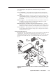
H V INPUT 2 R/VID G/Y VID VID C H B/C Y/C V R G B H Y/C V C VID C B A RS-232 Tx Rx G Ps G +V S G S G S G L 2 1 R L R L 3 D A B C D E S G +V G CM IR SCP R L 4 LAN RELAYS CM/IR/SCP IR/SERIAL OUT PROJ CONT Y AUDIO B/C Y OUTPUT G/Y INPUT 4 R/VID INPUT 3 1.3A INPUT 1 100-240V A B C C 1 2 C 3 4 C 5 CONFIG/RS-232 R L LINEOUT R R 6 L PREAMP R 50-60Hz Extron System 5 IP System Switcher MVC 121 MAIN 3 FIXED INPUTS 12V 0.
Special Applications, cont’d Configuring the System 5 for switcher slaving 1. Cable and power on the System 5 IP, the MPS 112, and a host PC. Refer to “Connecting the System 5 IP and MPS 112” in this chapter. 2. On the host PC, start the Global Configurator program, and open the appropriate project file. 3. Click on the IP Link tab on the left side of the screen. 4. Click or double-click on the System 5 IP you wish to configure to show and expand the menu of connected devices.
System 5 IP Switchers A Appendix A Reference Material Specifications Part Numbers and Accessories Audio Block Diagram Glossary
Reference Material Specifications Video Gain ............................................... Bandwidth .................................... Differential phase error .............. Differential gain error ................. Crosstalk ....................................... Switching speed ........................... Unity 350 MHz (-3 dB), fully loaded 1º at 3.58 MHz and 4.43 MHz 1% at 3.58 MHz and 4.43 MHz -68 dB @ 10 MHz, -39 dB @ 100 MHz <600 ms (max.) PRELIMINARY Video input Number/signal type .........
Standards ...................................... Input level ..................................... Output level .................................. Input impedance .......................... Output impedance ...................... Max input voltage ....................... Max. propagation delay .............. Max. rise/fall time ....................... Polarity .......................................... TTL (RGB), NTSC 3.58, NTSC 4.43, PAL, SECAM 2.0 V to 5.0 Vp-p 5.0 Vp-p, unterminated 10k ohms 75 ohms 5.
Reference Material, cont’d Nominal level ............................... -10 dBV (316 mV) or +4 dBu (1.23 V) (configurable) Maximum level (600 ohm) ......... >+18 dBu, balanced at 1%THD+N Unbalanced wired outputs will have unity gain/attenuation. Balanced outputs will result in a 6 dB gain. Audio output — power amplifier (amplifier models only) Number/signal type ................... 1 stereo or mono (default = stereo, configurable via front panel or control software) Connector ............................
Control — peripheral equipment IR/serial control ports ................ (4) 3.5 mm captive screw connectors, 2-pole Programmable: RS-232 (±5 V), or TTL level (0 to 5 V) infrared up to 1 MHz IR learning frequencies ............... 30 kHz to 62 kHz IR learning distance ..................... 4" (10 cm) to 14" (36 cm) from the front panel Power ............................................. 100 VAC to 240 VAC, 50/60 Hz, 50 watts, internal, autoswitchable Temperature/humidity ..............
Reference Material, cont’d Part Numbers and Accessories Included parts These items are included in each order for a System 5 IP switcher: Included parts System 5 IP with amplifier, with FPC (1) Replacement part number 60-397-81 or System 5 IP without amplifier, with FPC (1) 60-397-83 or System 5 IP with amplifier, without FPC (1) 60-397-82 or System 5 IP without amplifier, without FPC (1) 60-397-84 Rubber feet (self-adhesive) (4) PRELIMINARY Rack mounting kit (brackets and screws) (1) 70-077-0
Control accessories Part number IR Emitter 19-823-01 IR Broadcaster 60-272-01 Current/display power sensor 60-271-01 IR Link IR signal repeater (gray, black, white) 70-207-01 SCP 150 (gray, black, white) 60-495-01, -02, -03 SCP 150 AAP (gray, black, white) 60-496-01, -02, -03 IRCM-VCR (gray, black, white) 70-148-01, -02, -03 IRCM-DVD (gray, black, white) 70-149-01, -02, -03 IRCM-DVD+ (gray, black, white) 70-179-01, -02, -03 IRCM-Tape (gray, black, white) 70-180-01, -02, -03 IRCM-DV+ (g
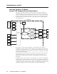
Reference Material, cont’d Audio Block Diagram CTRL +- +- +- +- +- +- 1 INPUT SELECT (LEFT CHANNEL) 2 3 +- +- LEFT CHN 4 PRELIMINARY SWITCHABLE INPUTS LINEOUT +- +LEFT 5 +- +- +- +- +- +- +- +- 1 INPUT SELECT (RIGHTCHANNEL) 2 3 RIGHT CHN 4 5 RIGHT CTRL LEFT CTRL MUX Per Input Gain/Attenuation Adjustment VOLUME MONO CTRL PREAMP LEFT BASS & TREBLE + - RIGHT BASS & TREBLE +/-10dB@ 100Hz/10kHz -40dB to +30dB + - MONO MUX RIGHT VOLUME CONTROL User Mode: Volume
Glossary 10/100Base-T is Ethernet which uses unshielded twisted pair (UTP – Cat 5, etc.) cable, where the amount of data transmitted between two points in a given amount of time is equal to either 10 Mbps or 100 Mbps. Address Resolution Protocol (ARP) is a protocol which assigns an IP address to a device based on the device’s MAC or physical machine address.
Reference Material, cont’d the Internet, a table (see ARP) relates the device’s IP address to its corresponding physical (MAC) address on the LAN. Pass-through allows control systems to work with the switcher and provides a link between two ports. Ping (ICMP) is a utility/diagnostic tool that tests network connections. It is used to determine if the host has an operating connection and is able to exchange information with another host.
System 5 IP Switchers B Appendix B Firmware Updates Determining the Firmware Version Updating the Main Firmware Updating FPGA Firmware
Firmware Updates If the need arises, you can replace the Extron System 5 IP switcher’s main firmware via an IP connection without opening the unit or changing firmware chips. It is unlikely that you will need to replace the FPGA firmware chip, which controls the switcher’s hardware (ports, relays), but it can be replaced after opening the unit.
1. Connect the switcher to a PC via an Ethernet connection, or connect the switcher and the PC to a network/LAN. See chapters two and four of this manual and read the System 5 IP Setup Guide for details. 2. Start a Web browser program (such as Microsoft® Intenet Explorer or Netscape® Navigator®). 3. Type the switcher’s IP address into the browser’s address area and log on to the System 5 IP’s internal Web page (see chapter four) or to the optional GlobalViewer Web page stored in the System 5 IP.
Firmware Updates, cont’d Updating the Main Firmware The PC and the switcher must both be connected to an Ethernet network in order to update the main firmware. Firmware upgrades can be performed via IP only. You may wish to save the existing configuration to a file (see chapter four) before replacing the firmware. Check the Extron Web site for firmware-related documents, instructions, patch files, and new firmware files before loading new firmware into the switcher.
In the Choose file dialog box, locate and select the firmware file you downloaded to C:\Program Files\Extron \Firmware\System_5_IP \xx, and click the Open button. 6. Click on the Web page’s Upload button to upload the firmware into the switcher. It takes a while to load all the files into the switcher. You will not see any on-screen indication when the upload has finished.
Firmware Updates, cont’d Locate chip U8 on the circuit board, as shown in the following illustrations. PRELIMINARY 4. Align Notches U8 10 0-24 0V 1.
Align the slots of the new FPGA chip with the socket in the same orientation as the old chip. 9. Gently but firmly press the chip into place in the socket. 10. Replace the top cover on the switcher, and fasten it with the screws that were removed in step 3. 11. Rack, wall, or furniture mount the switcher, and reconnect the AC power cord. PRELIMINARY 8.
PRELIMINARY Firmware Updates, cont’d B-8 System 5 IP Switchers • Firmware Updates
FCC Class A Notice Note: This equipment has been tested and found to comply with the limits for a Class A digital device, pursuant to part 15 of the FCC Rules. These limits are designed to provide reasonable protection against harmful interference when the equipment is operated in a commercial environment. This equipment generates, uses and can radiate radio frequency energy and, if not installed and used in accordance with the instruction manual, may cause harmful interference to radio communications.
www.extron.com Extron Electronics, USA Extron Electronics, Europe Extron Electronics, Asia Extron Electronics, Japan 1230 South Lewis Street Anaheim, CA 92805 USA 714.491.1500 Fax 714.491.1517 Beeldschermweg 6C 3821 AH Amersfoort The Netherlands +31.33.453.4040 Fax +31.33.453.4050 135 Joo Seng Road, #04-01 PM Industrial Building Singapore 368363 +65.6383.4400 Fax +65.6383.4664 Kyodo Building 16 Ichibancho Chiyoda-ku, Tokyo 102-0082 Japan +81.3.3511.7655 Fax +81.3.3511.