User’s Manual SW2 VGA DA2 AF R www.extron.com Extron Electronics, USA Extron Electronics, Europe Extron Electronics, Asia Extron Electronics, Japan 1230 South Lewis Street Anaheim, CA 92805 USA 714.491.1500 Fax 714.491.1517 Beeldschermweg 6C 3821 AH Amersfoort The Netherlands +31.33.453.4040 Fax +31.33.453.4050 135 Joo Seng Road, #04-01 PM Industrial Building Singapore 368363 +65.6383.4400 Fax +65.6383.4664 Daisan DMJ Building 6F 3-9-1 Kudan Minami Chiyoda-ku, Tokyo 102-0074 Japan +81.3.3511.
Precautions Safety Instructions • English This symbol is intended to alert the user of important operating and maintenance (servicing) instructions in the literature provided with the equipment. This symbol is intended to alert the user of the presence of uninsulated dangerous voltage within the product's enclosure that may present a risk of electric shock. Caution Read Instructions • Read and understand all safety and operating instructions before using the equipment.
Table of Contents Chapter 1 • Introduction .......................................................... 1-1 About this Manual ................................................................ 1-2 About the SW2 VGA DA2 AF R ........................................ 1-2 Features ...................................................................................... 1-2 Chapter 2 • Installation and Operation .......................... 2-1 Installation Overview ......................................................
Table of Contents, cont’d SW2 VGA DA2 AF R 1 Chapter One Introduction About this Manual About the SW2 VGA DA2 AF R Features ii SW2 VGA DA2 AF R • Table of Contents
Introduction, cont’d Introduction About this Manual This manual contains information about Extron’s SW2 VGA DA2 AF R switcher and details on how to operate and configure it. SW2 VGA DA2 AF R About the SW2 VGA DA2 AF R The SW2 VGA DA2 AF R is a full rack width two-input VGA switcher with two buffered outputs and 300 MHz (-3dB) video bandwidth. It accepts two VGA, SVGA, XGA, or UXGA computer-video and two stereo audio inputs. It also features two buffered VGA outputs and one stereo audio output.
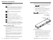
Installation and Operation, cont’d Installation and Operation Installation Overview To install and set up the SW2 VGA DA2 AF R for operation, follow these steps: 1 2 3 Turn all of the equipment off. Make sure that the video and audio sources (computers, stereos, tape decks or other devices), the SW2 VGA DA2 AF R, the output devices (projectors, speakers), and contact closure control device are all turned off and disconnected from the power source. rack or in furniture.
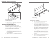
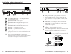
Installation and Operation, cont’d Cable Routing UN SW ITCH 0.5 GA 2V SW IN PU T FR 2A DA 10 0-2 ED A MA X. 40 2 2 1 ITCH SW TO VE AU ACTI ITCH SW UN ED X. A MA 0.5 A 2 VG SW Tighten nuts securely INPU T 2 AF DA R -24 100 0 2 2 1 ITC SW TO E AU ACTIV H Adapter Plate Rack mounting Front or Rear AAP Installation Routing adapter output cables and attaching adapter plate 6. Replace the top cover on the switcher, and fasten it with the screws removed in step 2.
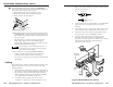
Installation and Operation, cont’d R F A 2 A D 2 W S A G V D E H C IT W S N U 0 24 010 A 0.5 X. MA D HE ITC SW UN 0.5 2 AF DA R 100 -24 A MA X. 0 T U P IN 2 A 2 VG SW 2 1 2 T PU IN 2 H C IT W S VE TO TI U C A A 1 H ITC SW TO E AU ACTIV Through-desk mounting Under-desk mounting To adjust the height of the switcher within the desk, slightly loosen the screws that attach the brackets to the switcher, adjust the height by sliding the switcher up or down, and retighten the screws.
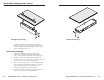
Installation and Operation, cont’d Rear Panel Features Front Panel Features INPUT 1 100-240 OUTPUTS 50/60 Hz 0.5A A B 5 6 AS/REMOTE 1 2 A S UNSWITCHED AUTO SWITCH ACTIVE 1 INPUT 2 2 SW2 VGA DA2 AF R 1 0.5A MAX. 2 3 4 7 8 5 3 1 6 2 100-240 7 8 9 4 1 Cable access opening — Cables attached to the A/V passthrough architectural adapter plates exit the enclosure here.
Installation and Operation, cont’d 8 decks) to the audio input jacks. The audio plug should be wired as shown below. Autoswitching/Contact closure connector (AS/REMOTE) — Connect a contact closure control device to the left three pins of this 3.5 mm, 5-pole captive screw connector. • Pin 1 selects input 1 when connected to ground. • Pin 2 selects input 2 when connected to ground. • Pin 3 connects to the ground wire.
Installation and Operation, cont’d Operation 1. Make sure that all the input and output devices and the switcher are powered on. 2. If the switcher is in manual switching mode, select an input from the front panel buttons or by using the contact closure controller. 3. If the switcher is in auto-switching mode (rear panel AS/REMOTE pins 4 and 5 are jumpered together), the switcher will automatically select the highest numbered input with an active sync signal. 4.
Specifications Video Gain ................................................ Unity Bandwidth ..................................... 300 MHz (-3dB) Video input Number/signal type ................... 2 VGA-UXGA RGBHV, RGBS, RGsB*, RsGsBs* Connectors ................................... 2 VGA 15-pin HD female Nominal level ............................... 0.7V p-p for RGB (excluding sync) Minimum/maximum levels ....... Analog ....... 0.3V to 1.5V p-p with no offset Impedance ....................................
Accessories and Part Numbers Enclosure type .............................. Metal Enclosure dimensions ................. 1.75” H x 17.5” W x 4.5” D (1U high, full rack width) 4.4 cm H x 44.5 cm W x 11.4 cm D (Depth excludes connectors.) Product weight ............................. 2.6 lbs (1.2 kg) Shipping weight ........................... 7 lbs (3.2 kg) Vibration ....................................... ISTA/NSTA 1A in carton (International Safe Transit Association) Listings ................................
A-6 SW2 VGA DA2 AF R • Accessories and Part Numbers -03 -02 -01 70-109 RCA female and 3 solder cups 1 1 RCA female and 1 3.5mm mini stereo jack RCA female and 3.5mm mini stereo jack -22 -12 -02 70-108 BNC female and 3 solder cups 1 1 BNC female and 1 3.5mm mini stereo jack BNC female and 3.
A-8 SW2 VGA DA2 AF R • Accessories and Part Numbers 1 2 2 2 1 1 2 1 D-9 (male to male) 1 3-pin XLR female 1 4-pin XLR female 1 6-pin XLR female 2 6-pin mini DIN (keyboard/mouse) 1 3.
Accessories and Part Numbers A-10 SW2 VGA DA2 AF R • Accessories and Part Numbers