
User Guide Rev. A User Manual

SW2 VGA DA2 AF R • Installation and Operation
SW2 VGA DA2 AF R • Installation and Operation
Installation and Operation, cont’d
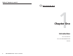
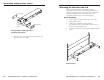
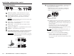
Front Panel Features
UNSWITCHED
100-240V 5A MAX.
AUTO
SWITCH
SW2 VGA DA2 AF R
12
INPUT
2
1 2 43 5 6 7 8 9
1
Auto-switching indicator LED — This LED lights when the
auto-switching feature is active.
2
Input 1 selection switch — Selects input 1
3
Input 1 indicator LED — This lights when input 1 is selected.
4
Input 2 selection switch — Selects input 2
5
Input 2 indicator LED — This lights when input 2 is selected.
6
Input 2 video — 15-pin HD female VGA connector
7
Input 2 audio — 3.5 mm female audio jack
8
AC power output connector — An unswitched standard IEC AC
power connector allows you to connect a peripheral device that
requires power.
This unit can operate at 100 to 240 VAC, 50/60 Hz with
the proper power cords.
9
Optional architectural adapter plates — One or two adapter
plates for pass-through audio/video connections can be
attached at one time to the switcher. See the “Installing Adapter
Plates” section in this chapter for installation instructions.
2-7
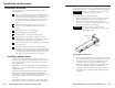
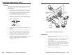
Under-desk mounting
1. Attach the under-desk mounting brackets
(part #70-212-01) to the SW2 VGA DA2 AF R with the four
provided machine screws, as shown in the under-desk
mounting diagram.
2. Hold the switcher with attached brackets against the
mounting surface. Use a soft pencil to mark the location of
holes for screws on the desk or other furniture.
3. Drill 1/4" (6.4 mm) deep, 3/32" (2.38 mm) diameter pilot
holes in the table or desk at the marked screw locations
from the underside/inside (concealed side) of the
furniture, where the switcher will be located.
4. Attach the switcher to the desk with the provided wood
screws, as shown in the following illustration.
U
N
S
W
I
T
C
H
E
D
1
0
0
-
2
4
0
0
.5
A
M
A
X
.
A
U
T
O
S
W
IT
C
H
A
C
T
IV
E
SW2 VGA DA 2 AF
R
1
2
I
N
P
U
T
1
Under-desk mounting
2-6