User’s Manual SW2 VGA DA2 AF R 2-Input Switcher with 2 Buffered Outputs and Audio www.extron.com Extron Electronics, USA Extron Electronics, Europe Extron Electronics, Asia Extron Electronics, Japan 1230 South Lewis Street Anaheim, CA 92805 USA 714.491.1500 Fax 714.491.1517 Beeldschermweg 6C 3821 AH Amersfoort The Netherlands +31.33.453.4040 Fax +31.33.453.4050 135 Joo Seng Road, #04-01 PM Industrial Building Singapore 368363 +65.6383.4400 Fax +65.6383.
Precautions Safety Instructions • English This symbol is intended to alert the user of important operating and maintenance (servicing) instructions in the literature provided with the equipment. This symbol is intended to alert the user of the presence of uninsulated dangerous voltage within the product's enclosure that may present a risk of electric shock. Caution Read Instructions • Read and understand all safety and operating instructions before using the equipment.
Table of Contents Chapter 1 • Introduction .......................................................... 1-1 About this Manual ................................................................ 1-2 About the SW2 VGA DA2 AF R ........................................ 1-2 Features ...................................................................................... 1-2 Chapter 2 • Installation and Operation .......................... 2-1 Installation Overview ......................................................
Table of Contents, cont’d SW2 VGA DA2 AF R 1 Chapter One Introduction About this Manual About the SW2 VGA DA2 AF R Features ii SW2 VGA DA2 AF R • Table of Contents
Introduction, cont’d Introduction About this Manual This manual contains information about Extron’s SW2 VGA DA2 AF R switcher and details on how to operate and configure it. SW2 VGA DA2 AF R About the SW2 VGA DA2 AF R The SW2 VGA DA2 AF R is a high performance, full rack width, two-input VGA switcher with 300 MHz (-3 dB) video bandwidth. It accepts two VGA, SVGA, XGA, or UXGA computer-video inputs and two stereo audio inputs. It features two buffered VGA outputs and one stereo audio output.
Installation and Operation, cont’d Installation and Operation Installation Overview To install and set up the SW2 VGA DA2 AF R for operation, follow these steps: 1 2 Turn all of the equipment off. Make sure that the video and audio sources (computers, stereos, tape decks or other devices), the SW2 VGA DA2 AF R, the output devices (projectors, speakers), and contact closure control device are all turned off and disconnected from the power source. rack or in furniture.
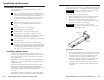
Installation and Operation, cont’d Mounting the SW2 VGA DA2 AF R When mounting the switcher, take cabling and power availability into consideration. Select either rack mounting using the included VersaTools® rack mount kit, or under-desk mounting using the optional mounting kit. Follow the appropriate installation steps on the following pages. Adapter Plate Rack mounting Tighten nuts securely 1. If feet were previously installed on the bottom of the switcher, remove them. 2.
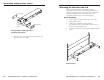
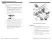
Installation and Operation, cont’d Under-desk mounting 1. 2. 3. 4. Front Panel Features Attach the under-desk mounting brackets (part #70-212-01) to the SW2 VGA DA2 AF R with the four provided machine screws, as shown in the under-desk mounting diagram. Hold the switcher with attached brackets against the mounting surface. Use a soft pencil to mark the location of holes for screws on the desk or other furniture. Drill 1/4" (6.4 mm) deep, 3/32" (2.
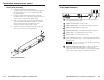
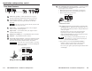
Installation and Operation, cont’d Rear Panel Features 8 SW2 VGA DA2 AF R INPUT OUTPUTS CONTACT AUTO-SW 1 100-240V 5.5A MAX. 50/60 Hz 1 2 3 A (LOCAL MONITOR) 4 5 B 6 1 2 7 8 Autoswitching/Contact closure connector — Connect a contact closure control device to the left three pins of this 3.5 mm, 5-pole captive screw connector. • Pin 1 selects input 1 when connected to ground (pin 3). • Pin 2 selects input 2 when connected to ground (pin 3). • Pin 3 connects to the ground wire.
Installation and Operation, cont’d Cabling Laptop Attach cables to the switcher as detailed in the steps below. The diagram in this section shows how the system looks when cabling is finished. 1. Attach the VGA/SVGA/XGA computers’ output cables to the switcher via the 15-pin HD female input connectors. If the computers will provide the audio input, VGA with audio combination cables, such as the Extron VGA HRA series (#26-490-01 to #26-490-04), can be used.
Installation and Operation, cont’d Troubleshooting SW2 VGA DA2 AF R If the image does not appear or there is no sound 1. Ensure that all devices are plugged in to a power source. 2. Make sure that each device is receiving power. If the switcher is in manual switch mode, one of the input indicator LEDs should light on the front panel of the SW2 VGA DA2 AF R. If the switcher is in auto-switching mode and there is no active incoming sync signal detected, the input indicator LEDs will not light.
Specifications Video Gain ................................................ Unity Bandwidth ..................................... 300 MHz (-3 dB) Video input Number/signal type ................... 2 VGA-UXGA RGBHV, RGBS, RGsB*, RsGsBs* Connectors ................................... 2 VGA female 15-pin HD Nominal level ............................... 0.7 Vp-p for RGB Minimum/maximum levels ....... Analog: 0.3 V to 1.5 Vp-p with no offset Impedance ....................................
Accessories and Part Numbers Temperature/humidity .............. Storage: -40 to +158 °F (-40 to +70 °C) / 10% to 90%, noncondensing Operating: +32 to +122 °F (0 to +50 °C) / 10% to 90%, noncondensing Rack mount SW2 VGA DA2 AF R ....... Yes, with included brackets (#70-485-01), and furniture mountable with optional brackets Enclosure type .............................. Metal Enclosure dimensions SW2 VGA DA2 AF R ....... 1.75" H x 17.4" W x 3.0" D (1U high, full rack wide) 4.4 cm H x 44.2 cm W x 7.
Accessories and Part Numbers Adapters Adapters Adapter Plates Part number Mac/VGA adapter 26-340-01 Mac HV/VGA adapter 26-340-02 SY-VGA/XGA (15-pin HD VGA male to 5 BNC male) 26-173-01 SY 15 HDM-RGBHVF (15-pin HD VGA male to 5 BNC female) 26-397-01 A variety of optional architectural adapter plates for pass-through connections may be ordered for the switcher. The SW2 VGA DA2 AF R can hold up to two (2) adapter plates on each side.
A-8 SW2 VGA DA2 AF R • Accessories and Part Numbers 1 2 1 1 1 1 1 S-video female and 1 BNC female 1 S-video female and 3 RCA female 1 S-video female and 2 RCA female 1 BNC female and 2 RCA female 1 BNC female and 1 3.5mm mini stereo jack 1 RCA female and 1 3.
1 1 1 1 2 2 1 1 1 1 2 2 2 1 1 2 2 F connector barrel 2 ¼" stereo phono female A-10 2 ¼" mono phono female 2 3.5mm mini stereo female 2 RJ-11 (female to female) 2 RJ-45 (female to female) 1 HD-15 (female to female) 1 HD-15 (male to male) 1 D-9 (female to female) 1 D-9 (male to male) 1 3-pin XLR female 1 4-pin XLR female 1 6-pin XLR female 2 6-pin mini DIN (keyboard/mouse) 1 3.5mm, 5 pole captive screw terminal 2 cable clamps solder cups cable clamps 3.
Accessories and Part Numbers A-12 SW2 VGA DA2 AF R • Accessories and Part Numbers