SW RGB and SW YUV A Series Wideband and Component Video and Audio Switchers 68-648-01 Rev.
Precautions Safety Instructions • English This symbol is intended to alert the user of important operating and maintenance (servicing) instructions in the literature provided with the equipment. This symbol is intended to alert the user of the presence of uninsulated dangerous voltage within the product's enclosure that may present a risk of electric shock. Warning Power sources • This equipment should be operated only from the power source indicated on the product.
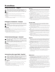
Quick Start — SW RGB and YUV A Switchers Installation Step 6 — Audio Outputs Step 1 — Remove power SW2 RGBHV A / SW4 RGBHV A / SW6 RGBHV A: Cable audio models for stereo audio output (6). Turn off power to the input and output devices, and remove the power cords from them. Step 2 — Mounting SW2 — If desired, mount the switcher in a rack using an Extron 1U Universal Rack Shelf, part # 60-190-01. If desired, mount the switcher under a desk using an Extron Under-desk Mount Kit, part #70-077-01.
Quick Start — SW RGB and YUV A Switchers, cont’d Step 7 — Remote Control Connect a host device, such as a computer or touch panel control via RS-232, OR a remote contact closure device to the switcher via this 9-pin D connector (7) for remote control of the switcher.
Table of Contents Chapter 1 • Introduction ....................................................................................................... 1-1 About the Switchers ......................................................................................................... 1-2 Features ................................................................................................................................... 1-3 Audio switching models ...............................................................
Table of Contents, cont’d Chapter 4 • Remote Control ................................................................................................ 4-1 Simple Instruction Set ...................................................................................................... 4-2 Host-to-switcher instructions ............................................................................................ 4-2 Switcher-initiated (unsolicited) messages ...........................................................
SW RGB and YUV A Switchers 1 Chapter One Introduction About the Switchers Features
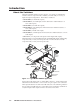
Introduction, cont’d Introduction About the Switchers The Extron SW RGB and YUV A series (figure 1-1) is a family of six RGB video switchers and one component video switcher, some with audio, in an array of input and output configurations.
Features Audio switching models Inputs — These switchers input 2, 4, or 6 stereo audio signals, balanced or unbalanced, on 3.5 mm, 5-pole captive screw terminals. Outputs — The selected audio input is buffered and output, balanced or unbalanced, on a 3.5 mm, 5-pole captive screw terminal. Audio gain/attenuation — Users can set the input level of audio gain or attenuation (-18 dB to +24 dB) via the RS-232 link or from the front panel, to be compatible with a wide range of line level (from -20 dBV to +4 dBV).
Introduction, cont’d All models Bandwidth — Bandwidth is 350 MHz (-3 dB). This high bandwidth allows the switchers to switch all of the high-resolution video signals with no loss of signal quality. Input signal sensing — The switcher continuously monitors all inputs to sense when the input signal is active or inactive. The switcher reports changes in the status of each input (active to inactive or inactive to active) on the RS-232 port.
SW RGB and YUV A Switchers 2 Chapter Two Installation Installation Overview Mounting the Switcher Cabling and Rear Panel Views
Installation, cont’d Installation Installation Overview Install an SW RGB or SW YUV A Series switcher as follows: 1 Turn off the input and output devices, and unplug their power cables. 2 If desired, mount the switcher in a rack, under furniture, or through furniture. See Mounting the Switcher below. 3 Connect the input and output devices to the switcher (see Cabling and Rear Panel Views on page 2-6).
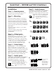
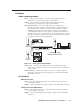
Use 2 mounting holes on opposite corners. False front panel uses 2 front holes. AU TO SW ITC H AC UT IVE 1 2 AU DIO CO RG (2) 4-40 x 3/16" Screws SW 2R V& GB AU HV DIO A BH SW NF ITCH /SAV ER E -dB +d B Figure 2-1 — Rack mounting an SW2 switcher Mounting Screws (2 Plcs) Each Side Drill pilot holes 3/32” (2.4mm) dia. 1/4” (6.3 mm) deep.
Installation, cont’d Under furniture mounting the switcher The SW2 switcher models can be mounted under a table or other horizontal surface with an optional Extron under-desk mounting kit (part #70-077-01). The SW4 and SW6 switcher models can be mounted under a table or other horizontal surface with an optional Extron 1U under-desk mounting kit (part #70-222-01). SW2 models 1.
3. Drill 1/4" (6.4 mm) deep, 3/32" (2 mm) diameter pilot holes in the table or desk at the marked screw locations from the underside/inside (concealed side) of the furniture, where the switcher will be located. 4. Insert the four wood screws into the pilot holes. Fasten each screw into the installation surface until just less than 1/4" of the screw head protrudes. 5.
Installation, cont’d Slide the switcher up and down or back and forth in the mounting brackets until the face of the switcher is at the desired height. Tighten the screws that secure the bracket in place. 5. If the screws are inaccessible to a screwdriver: a. Mark the location of the brackets relative to the screws. b. Remove the switcher from the underside of the surface. c. Tighten the screws. d. Replace the switcher on the underside of the surface (step 4).
Inputs 1 RGB and component video inputs — RGB models — For each input, connect an RGBHV, RGBS, RGsB, RsGsBs, or component video source to these BNC connectors. Connect the cables as shown in figure 2-8. SW6 YUV A — For each input, connect a component video, RGsB, or RsGsBs source to one of these BNC connectors. If you are not switching digital audio, you can use the Digital Audio input BNCs ( 3 ) for the composite sync plane of RGBS video inputs. Connect the cables as shown in figure 2-8.
Installation, cont’d The audio level for each input can be individually set, via the front panel or under RS-232 control, to ensure that the level on the output does not vary from input to input. See chapter 3, Operation, and chapter 4, Remote Control for details. 3 Digital audio input connections (SW6 YUV A only) — Each input has a female BNC connector for a digital audio input. If you are not switching digital audio, you can use this connector to input the composite sync plane of RGBS video.
Remote connection 7 Remote connector — Connect a host device, such as a computer or touch panel control, or a remote contact closure device to the switcher via this 9-pin D connector (figure 2-11) for remote control of the switcher. See chapter 4, Remote Control, for definitions of the SIS commands, details on how to install and use the control software, and information on how to make a remote contact closure device.
Installation, cont’d 2-10 SW RGB and YUV A Switchers • Installation
SW RGB and YUV A Switchers 3 Chapter Three Operation Controls and Indicators Switcher Operations Optimizing the Audio (SW2, SW4, and SW6 RGBHV A only) Troubleshooting — If No Image Appears
Operation, cont’d Operation Controls and Indicators The SW RGB or SW YUV A family of switchers have 2, 4, or 6 input buttons and LEDs on the front panel. Audio models also have front panel configuration controls and LEDs. All models have an Auto/Manual mode selection switch on the rear panel. Figure 3-1 shows the front panel of an SW2 RGBHV switcher. Figure 3-2 shows the front panel of an SW6 RGBHV A switcher.
Audio controls and indicators 3 Audio configuration/save button and LED — The Audio button and LED enable the user to view and/or change the current audio level setting for each input. See Audio gain and attenuation in this chapter. 4 Down ( ) button and LED — The button is used to decrease the audio level for a selected input. The LED flashes each time the button is pressed to indicated a 1 dB decrease in the audio level. See Audio gain and attenuation in this chapter.
Operation, cont’d Switcher Operations The following paragraphs detail the power up process and provide sample procedures for selecting an input and viewing and adjusting the audio level. Power Plug in the switcher. On all switcher models, power is automatically applied when the power cord is connected to an AC source. When AC power is applied, the switcher performs a self-test that blinks the front panel LEDs during the test.
2. Press and hold the Audio Conf/Save button until the Conf/ Save LED begins to blink, then release the Conf/Save button. The +dB and –dB LEDs display the polarity (+ or –). The lit +dB LED indicates a positive (gain) level. The lit –dB LED indicates a negative (attenuation) level. Both LEDs lit indicate 0 dB. Press and hold. B CONF/SAVE Conf/Save blinks. Release the button. On the SW4 RGBHV A and SW6 RGBHV A only, the input 1 through 4 LEDs display the approximate audio level for the selected input.
Operation, cont’d If the +dB and –dB LED are both lit they indicate 0 dB. Otherwise, you can determine the exact gain or attenuation using the following procedure. a. If one or more input LEDs are lit AND the +dB LED is/are lit, press and release the button repeatedly until the highest-numbered lit input LED goes out. Count the button presses. In this example, assume a value of +8 dB. It will take three presses of the button for the Input 1 LED to go out.
Audio level reset — single input Reset the audio level for an input to 0 dB as follows: The switcher must be in normal (manual) mode. 1. Press and release an input button to select an input. 2. Press and hold the Audio Conf/Save button until the Conf/Save LED begins to blink, then release the Conf/Save button. 3. Press and release the Input LEDs go off. 4. Press and hold the Audio Conf/Save button until the Conf/Save LED goes and LEDs go off, and the selected Input LED lights. off. The and buttons.
Operation, cont’d Troubleshooting — If No Image Appears 3-8 1. Ensure that all devices are plugged in and powered on. The switcher is receiving power if the front panel Power LED (if equipped) is lit. 2. Ensure an active input is selected on the switcher or that the switcher is in autoswitch mode. 3. Ensure that the proper signal format is supplied. 4. Check the cabling and make corrections as necessary. 5. Call the Extron S3 Sales & Technical Support Hotline if necessary.
SW RGB and YUV A Switchers 4 Chapter Four Remote Control Simple Instruction Set Windows-Based Control Program Contact Closure Infrared Remote Control
Remote Control, cont’d Remote Control The SW RGB and SW YUV A Series switchers can be remotely controlled via the switcher’s rear panel Remote connector (figure 4-1). Remote control devices can be: • • • A host device (such as a computer or control system) An IR 102 Universal remote control kit A contact closure device such as an Extron KP 6 Keypad Control or a locallyconstructed device.
Switcher-initiated (unsolicited) messages When a local event, such as a front panel operation or error condition, occurs, the switcher responds by sending a message to the host. The switcher-initiated messages are listed below. (C) Copyright 2002, Extron Electronics, SW6 RGBHV {or appropriate model}, Vx.xx The switcher issues the copyright message when it first powers on. Vx.xx is the firmware version number. Inn•All The switcher issues the Inn message when a front panel input selection operation occurs.
Remote Control, cont’d ASCII to HEX Conversion Table Space Symbol definitions Input and output numbers in commands may be entered as either 1-, 2-, or 3digit numbers. All input and output numbers are specified as 3-digit numbers in the response.
Command/Response table for SIS commands (Continued) Command ASCII Command Response Additional description (host to switcher) (switcher to host) Request all inputs’ status 0S Sig• X3 1• X3 2•...• X3 n Example (SW6 RGBHV): 0S Sig•1•1•1•0•1•0 X2 S X3 Each X3 response is the signal status of an input, starting from input 1; n is the maximum number of inputs for this model. The input signal is present on inputs 1, 2, 3, and 5. No signal is present on inputs 4 and 6. X2 ’s signal status = X3 .
Remote Control, cont’d Windows-Based Control Program The Universal Switcher Control Program, part #29-031-01, is compatible with MicrosSoft Windows 3.1, 3.11, 95/98, and above, and provides remote control of the following: • Input selection (including audio breakaway for models with video and audio) • Audio gain and attenuation adjustments (audio models) Updates to this program can be downloaded from the Extron Web site (http://www.extron.com).
Using the help system For information about program features, you can access the help program in any of the following ways: • From the Extron Electronics program group, double-click on the Universal Switcher Control Program Help icon. • From within the Windows-based switcher control program, click on the Help entry on the task bar. • From within the Windows-based switcher control program, press the F1 key.
Remote Control, cont’d 4-8 SW RGB and YUV A Switchers • Remote Control
SW RGB and YUV A Switchers A Appendix A Specifications and Part Numbers Specifications Part Numbers
Specifications, cont’d Specifications Video Gain ............................................... Bandwidth .................................... Differential phase error .............. Differential gain error ................. Crosstalk ....................................... Switching speed ........................... Unity. 350 MHz (-3 dB) 1.0º at 3.58 MHz and 4.43 MHz 1.0% at 3.58 MHz and 4.43 MHz -70 dB @ 10 MHz 5 ms (max.
Sync Input type ..................................... Output type .................................. Input level ..................................... Output level .................................. Input impedance .......................... Output impedance ...................... Max input voltage ....................... Max. propagation delay .............. Max. rise/fall time ....................... Polarity ..........................................
Specifications, cont’d Audio output — SW 2/4/6 RGBHV A only Number/signal type ................... Connectors .................................... Impedance .................................... Nominal level ............................... 1 stereo, balanced/unbalanced (1) 3.5 mm captive screw connector, 5 pole 50 ohms unbalanced, 50 ohms balanced -20 dBV (100mV), -10 dBV (316mV), 0 dBu (1V), or +4 dBu (1.23V), configurable Maximum level (Hi-Z) ................
Part Numbers SW RGBHV switcher part numbers Switcher SW2 RGBHV video switcher SW2 RGBHV A video and audio switcher Part # 60-491-01 60-491-21 SW4 RGBHV video switcher SW4 RGBHV A video and audio switcher 60-492-01 60-492-21 SW6 RGBHV video switcher SW6 RGBHV A video and audio switcher 60-493-01 60-493-21 SW6 YUV A component video and digital audio switcher 60-498-01 Supplied accessories Switcher SW RGBHV switcher User’s Manual Universal Switcher Control Program Rack mounting bracket kit (SW4 and SW6
Specifications, cont’d Plenum BNC-5 Mini HR Cable Plenum BNC-5 Mini HR bulk, 500', 1000' Part # 22-103-02, -03 BNC-5 RC and BNC-6 RC Cable BNC-5 RC bulk, 500', 1000' Part # 22-127-02, -03 Assorted connectors BNC connectors RG6/SHR male crimp connectors, qty. 50 BNC Mini HR crimp connectors, qty. 50 BNC Male RC crimp connectors, qty. 50 BNC bulkhead connectors, qty. 50 Part # 100-075-51 100-074-51 100-452-51 100-076-51 Pre-cut cables All Extron BNC cables have male connectors on both ends.
FCC Class A Notice Note: This equipment has been tested and found to comply with the limits for a Class A digital device, pursuant to part 15 of the FCC Rules. These limits are designed to provide reasonable protection against harmful interference when the equipment is operated in a commercial environment. This equipment generates, uses and can radiate radio frequency energy and, if not installed and used in accordance with the instruction manual, may cause harmful interference to radio communications.
www.extron.com Extron Electronics, USA Extron Electronics, Europe Extron Electronics, Asia Extron Electronics, Japan 1230 South Lewis Street Anaheim, CA 92805 USA 714.491.1500 Fax 714.491.1517 Beeldschermweg 6C 3821 AH Amersfoort The Netherlands +31.33.453.4040 Fax +31.33.453.4050 135 Joo Seng Road, #04-01 PM Industrial Building Singapore 368363 +65.6383.4400 Fax +65.6383.4664 Daisan DMJ Building 6F 3-9-1 Kudan Minami Chiyoda-ku, Tokyo 102-0074 Japan +81.3.3511.7655 Fax +81.3.3511.