SW RGBHV series Wideband Video and Audio Switchers 68-648-01 Rev.
Precautions Safety Instructions • English Warning This symbol is intended to alert the user of important operating and maintenance (servicing) instructions in the literature provided with the equipment. Power sources • This equipment should be operated only from the power source indicated on the product. This equipment is intended to be used with a main power system with a grounded (neutral) conductor. The third (grounding) pin is a safety feature, do not attempt to bypass or disable it.
FCC Class A Notice N This equipment has been tested and found to comply with the limits for a Class A digital device, pursuant to part 15 of the FCC Rules. These limits are designed to provide reasonable protection against harmful interference when the equipment is operated in a commercial environment. This equipment generates, uses and can radiate radio frequency energy and, if not installed and used in accordance with the instruction manual, may cause harmful interference to radio communications.
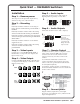
Quick Start — SW RGBHV Switchers Installation Step 5 — Audio Inputs Step 1 — Remove power Cable audio models for stereo audio input (5). High impedance is generally over 10k ohms. Turn off power to the input and output devices, and remove the power cords from them. 5 Tip Sleeve Tip Sleeve Step 2 — Mounting SW2 — If desired, mount the switcher in a rack using an Extron 1U Universal Rack Shelf, part # 60-190-01 or 60-604-02.
Quick Start — SW RGBHV Series Switchers, cont’d Operation Switch mode Set the rear panel switch to Auto for autoswitch mode (the switcher automatically switches to the highest-numbered input with a sync AUTO signal present) or Normal for manual switch mode. The front panel Auto Switch Active LED lights when the MANUAL switcher is in autoswitch mode. Switch inputs in normal switch mode Press and release the desired input button. Adjust audio level (SW2 RGBHV A / SW4 RGBHV A / SW6 RGBHV A only) 1.
Table of Contents Chapter 1 • Introduction ....................................................................................................... 1-1 About the Switchers ......................................................................................................... 1-2 Features ................................................................................................................................... 1-3 Audio switching models ...............................................................
Table of Contents, cont’d Chapter 4 • Remote Control ................................................................................................ 4-1 Simple Instruction Set ...................................................................................................... 4-2 Host-to-switcher instructions ............................................................................................ 4-2 Switcher-initiated (unsolicited) messages ...........................................................
SW RGBHV Series Switchers 1 Chapter One Introduction About the Switchers Features
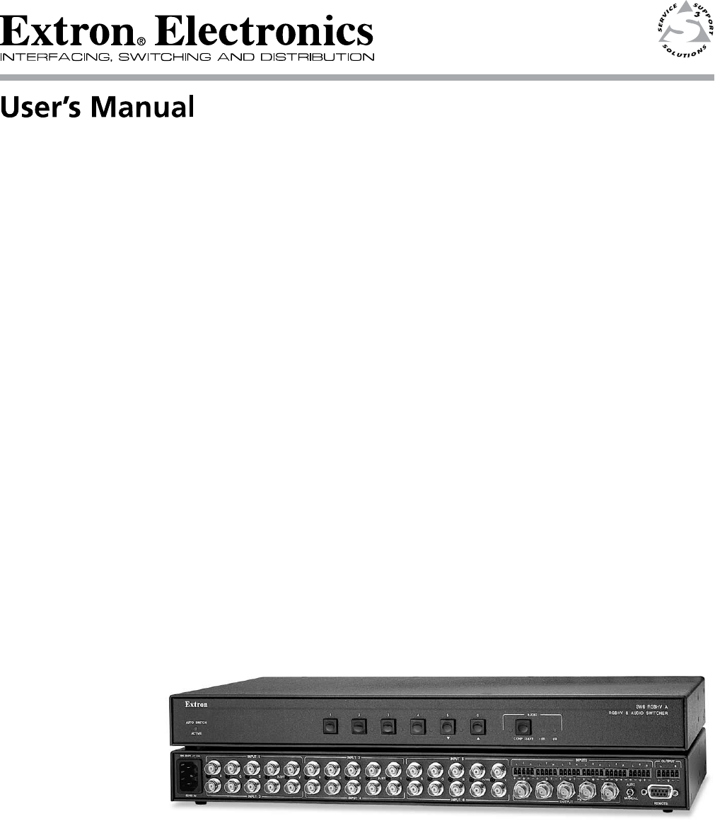
Introduction, cont’d Introduction About the Switchers The Extron SW RGBHV series (figure 1-1) is a family of six RGB video switchers, some with audio, in an array of input and output configurations.
Features Audio switching models Inputs — These switchers input 2, 4, or 6 stereo audio signals, balanced or unbalanced, on 3.5 mm, 5-pole captive screw terminals. Outputs — The selected audio input is buffered and output, balanced or unbalanced, on a 3.5 mm, 5-pole captive screw terminal. Audio gain/attenuation — Users can set the input level of audio gain or attenuation (-18 dB to +24 dB) via the RS-232 link or from the front panel, to be compatible with a wide range of line level (from -20 dBV to +4 dBV).
Introduction, cont’d Autoswitching mode — When autoswitching is enabled, the switcher continuously monitors all inputs and automatically switches to the highest-numbered input with video sync pulses present. If video is absent from all inputs, no input is selected. Operational flexibility — The operator can select the input and set the audio gain and attenuation for each input using the front panel buttons or via the switcher’s Remote port RS-232 link.
SW RGBHV Series Switchers 2 Chapter Two Installation Installation Overview Mounting the Switcher Cabling and Rear Panel Views
Installation, cont’d Installation Installation Overview Install an SW RGBHV Series switcher as follows: 1 Turn off the input and output devices, and unplug their power cables. 2 If desired, mount the switcher in a rack, under furniture, or through furniture. See “Mounting the Switcher”, below. 3 Connect the input and output devices to the switcher (see “Cabling and Rear Panel Views”, on page 2-7).
SW2 models 1. If rubber feet were installed on the bottom of the switcher, remove them. 2. Place the switcher on one half of the optional RSU 129 or RSB 129 1U (one unit high, 19" wide) rack shelf (part #60-190-01 or 60-604-02). Align the front of the switcher with the front of the shelf, and align the threaded holes on the bottom of the switcher with the holes in the rack shelf (figure 2-1). Use 2 mounting holes on opposite corners. False front panel uses 2 front holes.
Installation, cont’d SW4 and SW6 models 1. If rubber feet were installed on the bottom of the switcher, remove them. 2. Attach the rack mount brackets to the switcher with eight provided #8 machine screws, provided (figure 2-2). Mounting Screws (2 Plcs) Each Side Drill pilot holes 3/32” (2.4mm) dia. 1/4” (6.3 mm) deep.
AUT O SW ICH ACU TIV E 1 2 RG SW BH V& AU 2 RG DIO BH V SW ITC HE R Under Desk Kit Figure 2-3 — Under-furniture mounting SW4 and SW6 models 1. Secure the optional table/wall mounting brackets to the switcher with the eight #8 machine screws provided in the mounting kit (figure 2-2 on page 2-4). 2. Hold the switcher with attached brackets against the underside of the desk or other furniture. Mark the location of holes for screws on the underside of the desk. 3. Drill 1/4" (6.
Installation, cont’d Through-furniture mounting the switcher The switchers can be mounted through a desk or other furniture. The SW2 models require an optional through-desk mounting kit, part #70-077-02. The SW4 and SW6 models require the included through-desk and rack mounting bracket. Mount the switcher as follows (figure 2-4): AC AU TIV TO SW ITC E H 1 2 RG BH V& AU HV GB ER 2 R ITCH SW DIO SW Figure 2-4 — Through-desk mounting 1.
c. Tighten the screws. d. Replace the switcher on the underside of the surface (step 6). Cabling and Rear Panel Views All connectors are on the rear panel. The switcher can be connected to up to six RGBHV or component video devices and (audio models only) stereo audio devices, depending on the model. The video and/or audio output output is identical to the selected input; the switchers perform no sync or video format manipulation.
Installation, cont’d 2 Balanced or unbalanced audio input connections (SW2 RGBHV A, SW4 RGBHV A, and SW6 RGBHV A only) — Each input has a 3.5 mm, 5-pole captive screw connector for balanced or unbalanced stereo audio input. Connectors are included with each SW RGBHV Series switcher, but you must supply the audio cable. See figure 2-8 to wire a connector for the appropriate input type and impedance level. High impedance is generally over 10k ohms.
Remote connection 5 Remote connector — Connect a host device, such as a computer or touch panel control, or a remote contact closure device to the switcher via this 9-pin D connector (figure 2-10) for remote control of the switcher. See chapter 4, “Remote Control”, for definitions of the SIS commands, details on how to install and use the control software, and information on how to construct a remote contact closure device.
Installation, cont’d 2-10 SW RGBHV Series Switchers • Installation
SW RGBHV Series Switchers 3 Chapter Three Operation Controls and Indicators Switcher Operations Optimizing the Audio (SW2, SW4, and SW6 RGBHV A only) Troubleshooting — If No Image Appears
Operation, cont’d Operation Controls and Indicators The SW RGBHV family of switchers have 2, 4, or 6 input buttons and LEDs on the front panel. Audio models also have front panel configuration controls and LEDs. All models have an Auto/Manual mode selection switch on the rear panel. Figure 3-1 shows the front panel of an SW2 RGBHV switcher. Figure 3-2 shows the front panel of an SW6 RGBHV A switcher.
Audio controls and indicators 3 Audio configuration/save button and LED — The Audio button and LED enable the user to view and/or change the current audio level setting for each input. See “Audio gain and attenuation (SW2 RGBHV A, SW4 RGBHV A, and SW6 RGBHV A only)”, later in this chapter. 4 Down ( ) button and LED — The button is used to decrease the audio level for a selected input. The LED flashes each time the button is pressed to indicated a 1 dB decrease in the audio level.
. Operation, cont’d Switcher Operations The following paragraphs detail the power up process and provide sample procedures for selecting an input and viewing and adjusting the audio level. Powering on the switcher 1. Plug in the switcher. On all switcher models, power is automatically applied when the power cord is connected to an AC source. When AC power is applied, the switcher performs a self-test that blinks the front panel LEDs during the test.
The audio level can be adjusted from the front panel or by using Extron’s Windows-based control program. The switcher must be in normal (manual) mode. 1. Press and release an input button to select an input. 2. Press and hold the Audio Conf/Save button until the Conf/ Save LED begins to blink, then release the Conf/Save button. The +dB and –dB LEDs display the polarity (+ or –). The lit +dB LED indicates a positive (gain) level. The lit –dB LED indicates a negative (attenuation) level.
Operation, cont’d If the +dB and –dB LED are both lit they indicate 0 dB. Otherwise, you can determine the exact gain or attenuation using the following procedure. a. If one or more input LEDs are lit AND the +dB LED is/are lit, press and release the button repeatedly until the highest-numbered lit input LED goes out. Count the button presses. In this example, assume a value of +8 dB. It will take three presses of the button for the Input 1 LED to go out.
Audio level reset — single input Reset the audio level for an input to 0 dB as follows: The switcher must be in normal (manual) mode. 1. Press and release an input button to select an input. 2. Press and hold the Audio Conf/Save button until the Conf/Save LED begins to blink, then release the Conf/Save button. 3. Press and release the Input LEDs go off. 4. Press and hold the Audio Conf/Save button until the Conf/Save LED goes off. The and LEDs go off, and the selected Input LED lights. and buttons.
Operation, cont’d Troubleshooting — If No Image Appears 3-8 1. Ensure that all devices are plugged in and powered on. The switcher is receiving power if the front panel Power LED (if equipped) is lit. 2. Ensure an active input is selected on the switcher or that the switcher is in autoswitch mode. 3. Ensure that the proper signal format is supplied. 4. Check the cabling and make corrections as necessary. 5. Call the Extron S3 Sales & Technical Support Hotline if necessary.
SW RGBHV Series Switchers 4 Chapter Four Remote Control Simple Instruction Set Windows®-Based Control Program Contact Closure Infrared Remote Control
Remote Control, cont’d Remote Control The SW RGBHV A Series switchers can be remotely controlled via the switcher’s rear panel Remote connector (figure 4-1). Remote control devices can be: • • • A host device (such as a computer or control system) An IR 102 Remote Control Kit A contact closure device such as an Extron KP 6 Keypad Control or a locallyconstructed device.
Switcher-initiated (unsolicited) messages When a local event, such as a front panel operation or error condition, occurs, the switcher responds by sending a message to the host. The switcher-initiated messages are listed below. (C) Copyright 2002, Extron Electronics, SW6 RGBHV {or appropriate model}, Vx.xx The switcher issues the copyright message when it first powers on. Vx.xx is the firmware version number. Inn•All The switcher issues the Inn message when a front panel input selection operation occurs.
Remote Control, cont’d ASCII to HEX Conversion Table Space Symbol definitions Input and output numbers in commands may be entered as either 1-, 2-, or 3-digit numbers. All input and output numbers are specified as 3-digit numbers in the response.
Command/Response table for SIS commands (continued) Command ASCII Command Response Additional description (host to switcher) (switcher to host) Set video mute 1B Vmt1 Video mute on (blank screen). Clear video mute 0B Vmt0 Video mute off. Read video mute B X3 Mute status = Video mute X3 . Audio mute (audio switchers) Set audio mute 1Z Amt1 Audio mute on (no sound output). Clear audio mute 0Z Amt0 Audio mute off. Read audio mute Z X3 Mute status = X3 .
Remote Control, cont’d Windows®-Based Control Program The Windows®-based Extron Universal Switcher Control Program, which communicates with the switcher via the rear panel Remote RS-232 port, provides an easy way to set up ties and sets of ties.
Using the software 1. Connect a serial cable between a PC and the switcher’s Remote port. The cable’s pin assignments are shown in figure 4-1 on page 4-2. Power up the PC and the switcher. 2. To run the software, click Start>Programs>Extron Electronics> Universal Switcher Control Pgm. 3. Click on the COM port that is connected to the switcher’s RS-232 port. 4.
Remote Control, cont’d Infrared Remote Control The optional Extron IR 102 Remote Control Kit consists of the following components: • IR 102 system remote (hand-held remote control) • IR detector with 6' cable • IR 102 receiver box with 3' cable • External 12 VDC adapter power supply Install and operate the remote control in accordance with IR 102 User’s Guide (part #68-663-01), included with the remote control.
SW RGBHV Series Switchers A Appendix A Specifications and Part Numbers Specifications Part Numbers
Specifications, cont’d Specifications Video Gain ............................................... Bandwidth .................................... Crosstalk ....................................... Switching speed ........................... Unity. 350 MHz (-3 dB) -70dB @ 10 MHz 5 ms (max.
Audio — SW 2/4/6 RGBHV A only Gain ............................................... -18 to +24 dB, adjustable When audio gain is set to unity (0 dB), balanced output has a 0 dB gain; unbalanced output is attenuated by 6 dB. Frequency response ..................... 20 Hz to 20 kHz, ±0.05 dB THD + Noise ................................ 0.03% @ 1 kHz, 0.3% @ 20 kHz at nominal level S/N ............................................... >90 dB at maximum output Crosstalk .......................................
Specifications, cont’d Contact closure pin configurations 1 = input #1, 4 = input #2, 6 = input #3, 7 = input #4, 8 = input #5, 9 = input #6 Program control ........................... Extron’s control/configuration program for Windows® Extron’s Simple Instruction Set (SIS™) General Power ............................................. 100 VAC to 240 VAC, 50/60 Hz, 20 watts, internal Temperature/humidity ..............
Part Numbers SW RGBHV switcher part numbers Switcher SW2 RGBHV video switcher SW2 RGBHV A video and audio switcher Part # 60-491-01 60-491-21 SW4 RGBHV video switcher SW4 RGBHV A video and audio switcher 60-492-01 60-492-21 SW6 RGBHV video switcher SW6 RGBHV A video and audio switcher 60-493-01 60-493-21 Supplied accessories Switcher SW RGBHV switcher User’s Manual Universal Switcher Control Program MBD 149 1U through-desk and rack mounting kit (SW4 and SW6 models only) 3.
Specifications, cont’d MHR-5 mini high resolution cable MHR-5/500, five conductor, non-plenum, 500' (150 m) MHR-5/1000, five conductor, non-plenum, 1000' (300 m)' MHR-5P/500, one conductor, plenum, 500' (150 m) MHR-5P/1000, one conductor, plenum, 1000' (300 m)' MHRHF-5/500, one conductor, halon free, 500' (150 m) MHRHF-5/1000, one conductor, halon free, 1000' (300 m)' Part # 22-020-02 22-020-03 22-103-02 22-103-03 22-126-02 22-126-03 M59-5 mini 59 flex cable M59-5/500, 500' (150 m) Part # 22-127-02 Crim
Extron’s Warranty Extron Electronics warrants this product against defects in materials and workmanship for a period of three years from the date of purchase.
Extron USA - West Headquarters +800.633.9876 Inside USA / Canada Only +1.714.491.1500 +1.714.491.1517 FAX Extron USA - East Extron Europe Extron Asia Extron Japan Extron China Extron Dubai +800.633.9876 +800.3987.6673 +800.7339.8766 +81.3.3511.7655 +81.3.3511.7656 FAX +400.883.1568 +971.4.2991800 +971.4.2991880 FAX +1.919.863.1794 +1.919.863.1797 FAX +31.33.453.4040 +31.33.453.4050 FAX +65.6383.4400 +65.6383.