User’s Manual SW MTP T Series www.extron.com Extron Electronics, USA Extron Electronics, Europe Extron Electronics, Asia Extron Electronics, Japan 1230 South Lewis Street Anaheim, CA 92805 USA 714.491.1500 Fax 714.491.1517 Beeldschermweg 6C 3821 AH Amersfoort The Netherlands +31.33.453.4040 Fax +31.33.453.4050 135 Joo Seng Road, #04-01 PM Industrial Building Singapore 368363 +65.6383.4400 Fax +65.6383.4664 Daisan DMJ Building 6F 3-9-1 Kudan Minami Chiyoda-ku, Tokyo 102-0074 Japan +81.3.3511.
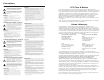
Precautions Safety Instructions • English This symbol is intended to alert the user of important operating and maintenance (servicing) instructions in the literature provided with the equipment. This symbol is intended to alert the user of the presence of uninsulated dangerous voltage within the product's enclosure that may present a risk of electric shock. Caution Read Instructions • Read and understand all safety and operating instructions before using the equipment.
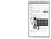
Quick Start Guide — SW MTP T Series Install and operate the SW MTP T Series switchers as follows: Step 1 Turn all of the equipment off and disconnect it from the power source. Step 2 Mount the switcher in a rack or furniture, or place on a desktop. Step 3 Video Input Connector Connect up to six video input cables, depending on the switcher model. Connect up to six audio input cables, depending on the switcher model.
Quick Start Guide — SW MTP T Series, cont’d CAUTION Connect the sleeve to ground. Connecting the sleeve to a negative (-) terminal will damage the audio output circuits. Unbalanced Output Tip Ring Sleeve (s) Tip Ring OUTPUT Cable the captive screw audio output connector for stereo, balanced or unbalanced audio output.
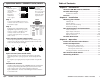
Table of Contents, cont’d Chapter 4 • Remote Control .................................................. 4-1 Simple Instruction Set Control ....................................... 4-2 Host-to-switcher communications ........................................ 4-2 Switcher-initiated (unsolicited) messages ............................ 4-3 Error responses ...................................................................... 4-3 Timeout ..............................................................................
Introduction About the SW MTP T Series Switchers The SW2 MTP T 15HD A, SW4 MTP T 15HD A, and SW6 MTP T 15HD A switchers are two, four, or six input, VGA or other high resolution video and computer audio switchers with a proprietary twisted pair (MTP) transmitter output that incorporates the selected video and mono audio signals and a separate stereo audio-only output.
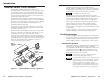
Introduction, cont’d Recommended transmission ranges at 60 Hz MTP R 15HD A and MTP RL 15HD A receivers Video format Composite, S-video, Component Pre-Peak off <300' (91.4 m) <300' (91.4 m) <300' (91.4 m) <250' (76.2 m) <250' (76.2 m) 640 x 480 800 x 600 1024 x 768 1280 x 1024 1600 x 1200 Pre-Peak Max. range Max. range on (high quality) (variable quality) >350' (106.7 m) >350' (106.7 m) >350' (106.7 m) >300' (91.4 m) >300' (91.4 m) 800' (243.8 m) 1000' (304.8 m) 700' (213.4 m) 550' (167.
Installation Mounting the Switcher The SW MTP T can be set on a table, mounted on a rack shelf, mounted to a rack without a shelf, or mounted under a desk, podium, or tabletop. VersaTools Rack Shelf Tabletop use Four self-adhesive rubber feet are included with the switcher. For tabletop use, attach one foot at each corner of the bottom side of the unit and place the unit in the desired location. Rack mounting For optional rack mounting, do not install the rubber feet.
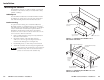
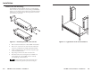
Installation Back of the rack mounting POWER 12V 0.2A MAX The SW MTP T can be mounted to the rear of a rack using the Extron VersaTools® back-of-the-rack mount kit (part #70-367-01) (figure 2-3). The kit allows the product to be vertically mounted to the front or rear rack supports and facing either towards the front or the rear of the rack.
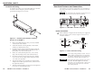
Installation, cont’d Furniture mounting Rear Panel Features and Connections For furniture mounting, do not attach the rubber feet. Furniture mount the switcher using the optional mounting kit (part #70-212-01) (figure 2-5) as follows: All connectors are on the rear panel (figure 2-6). Depending on the model of the switcher, the number of connectors on the rear panel varies. The SW2 MTP T and SW4 MTP T switchers have fewer input connectors but are otherwise identical.
Installation, cont’d Do not tin the stripped power supply leads before installing the captive screw connector. Tinned wires are not as secure in the captive screw connector and could be pulled out. 3 Audio input connectors — Plug a 3.5 mm stereo audio plug into this jack for unbalanced audio input. Wire the plug as shown in figure 2-8. The number of inputs available varies with the switcher model. Figure 2-8 shows a typical audio connector, which consists of the tip, ring and sleeve.
Installation, cont’d 6 Audio output connector — Insert a 3.5 mm, 5-pole, one-piece captive screw audio connector into this connector for stereo audio output. Wire the connector as shown in figure 2-9. CAUTION TP Cable Termination RJ-45 termination must comply with the TIA/EIA T 568A or TIA/EIA T 568B wiring standards for all connections. If you are using Enhanced SkewFree A/V UTP cable, then you should use the TIA/EIA T 568A standard only. Connect the sleeve to ground (Gnd).
Installation, cont’d SW MTP T Series Switchers 3 Chapter Three Operation Front Panel Controls and Indicators Front Panel Operations Rear Panel Pre-Peak Switch Skew Delay Problems 2-12 SW MTP T Series Switchers • Installation
Operation, cont’d Normal is a secondary function of the Input 2 button. Front Panel Controls and Indicators Figure 3-1 shows the controls and indicators on the front panel of the SW2 MTP T 15HD A and SW6 MTP T 15HD A switchers. The SW4 MTP T 15HD A switcher has fewer input buttons than the SW6 MTP T 15HD A, but is otherwise identical.
Operation, cont’d Rear Panel Pre-Peak Switch The Pre-Peak switch alters the TP signal output to correct for long cable runs. See item 5 on figure 2-6 on page 2-7 and on page 2-9 and the table on page 1-4 for suggested switch settings based on the transmitted video format and transmission distance. Skew Delay Problems CAT 5 TP cable can lead to registration errors between the red, green, and blue video signals.
Remote Control The SW MTP T Series switcher’s rear panel Remote connector (Figure 4-1) can be connected to the serial port of a host device, such as a computer or control system, to an Extron IR 102 Kit Universal Remote Control, OR to a remote contact closure device. Other than the IR 102 Kit, remote communications with the switcher are via Extron’s Simple Instruction Set (SIS™), Extron’s Windows-based control program, or pin-programmed in the case of a contact closure device.
Symbol definitions = CR/LF (carriage return/line feed) (0x0D 0A) 4-4 • = space X1 = Input number 0 through 6 (0 = output mute) X2 = Input signal status 0 = no signal detected, 1 = signal detected X3 = On/off status 0 = off 1 = on X4 = Firmware version x.xx X5 = Switch mode 1 = normal switch mode 2 = auto switch mode SW MTP T Series Switchers • Remote Control X1 % All X1 Vid X1 Vid X1 Aud X1 can be used interchangeably.
4-6 B Read video mute 1# 2# SW MTP T Series Switchers • Remote Control 1x 0x x X3 Exe1 Exe0 F1 F2 (host to switcher) (switcher to host) ASCII Command Response Master reset Esc Zxxx Q Reset N Query firmware version I Request for part number Information request Example Additional description Lock front panel. Unlock front panel. Read front panel lock: 1 = locked, 0 = unlocked. Set switch mode to normal. Set switch mode to auto (auto-switch).
Remote Control, cont’d Windows-Based Program Control The Universal Switcher Control Program, part #29-031-01, is compatible with Windows 3.1/3.11, Windows 95/98, Windows NT, Windows ME, Windows XP, and Windows 2000 and provides remote control and/or indication of the following: • Input selection (including audio breakaway for models with video and audio) • Front panel switch mode selection • Input sensing indication Using the software 1.
Remote Control, cont’d Updating the firmware The firmware upgrade utility provides a way to replace the firmware that is coded on the switcher’s control board without taking the switcher out of service, opening the switcher enclosure, and replacing the firmware chip. 4. Visit the Extron web site, www.extron.com, select the switcher product category, select the latest firmware file for download, and copy it to your computer. Note the folder to which you save the firmware file. 2.
Remote Control, cont’d Using the help system For information about program features, you can access the help program in any of the following ways: • From the Extron Electronics program group, double-click on the Universal Switcher Help icon. • From within the Windows-based switcher control program, click on the Help entry on the task bar. • From within the Windows-based switcher control program, press the F1 key.
Reference Information Specifications Video Number/signal type ................... 1 set of proprietary analog signals Connectors .................................... 1 female RJ-45 Video input Number/signal type ................... 2, 4, or 6 (depending on the model) analog VGA-UXGA RGBHV, RGBS, RGsB, component video, S-Video or composite video Connectors .................................... 2, 4, or 6 (depending on the model) female 15-pin HD Nominal level ...............................
Reference Information, cont’d Program control ........................... Extron’s control/configuration program for Windows® Extron’s Simple Instruction Set (SIS™) Part Numbers Switchers General Power ............................................. Supplied by an external power supply The SW MTP Series transmitters cannot supply remote power to or receive remote power from attached receivers. External power supply ...............
Reference Information, cont’d Enhanced Skew-Free™ A/V cable Part number Enhanced Skew-Free™ A/V UTP cables are not recommended for Ethernet/LAN applications.
Reference Information, cont’d A-8 SW MTP T Series Switchers • Reference Information