
User Guide Instruction Manual


SW HDMI LC • Installation 6
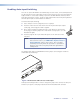
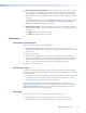
5. Use the supplied tie-wrap to strap the power cord to the extended tail of the
connector.
The figure below shows how to wire the connector.
Captive Screw Connector
Tie Wrap
Heat
Shrink
1/8”
(3 mm)
7/8”
(22 mm)
3/16”
(5 mm) Max.
Figure 4. Power Connector Wiring
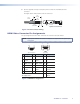
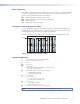
HDMI Video Connector Pin Assignments
The pin assignments for the video connectors are shown in the table below.
NOTE: Appropriate HDMI to DVI cables or adapters are required for DVI signal input
and output.
Pin
Signal
Pin Signal
Pin
Signal
1 TMDS data 2+ 7 TMDS data 0+ 13 CEC*
2 TMDS data 2 8 TMDS data 0 14 Reserved (NC)
shield shield
3 TMDS data 2– 9 TMDS data 0– 15 SCL
4 TMDS data 1+ 10 TMDS clock+ 16 SDA
5 TMDS data 1 11 TMDS clock 17 DDC/CEC
shield shield ground
6 TMDS data 1– 12 TMDS clock– 18 +5 V power
19
Hot plug
detect
HDMI
Type A Receptacle
1
18 2
19
HDMI
Type A Plug
1
182
19
*Not supported
Figure 5. HDMI Pin Configurations