User Guide HDMI Switchers SW HDMI LC Two and Four Input HDMI Switchers 68-1978-01 Rev.
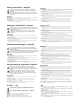
Safety Instructions • English This symbol is intended to alert the user of important operating and maintenance (servicing) instructions in the literature provided with the equipment. This symbol is intended to alert the user of the presence of uninsulated dangerous voltage within the product’s enclosure that may present a risk of electric shock. Warning Power sources • This equipment should be operated only from the power source indicated on the product.
FCC Class A Notice This equipment has been tested and found to comply with the limits for a Class A digital device, pursuant to part 15 of the FCC Rules. Operation is subject to the following two conditions: 1. This device may not cause harmful interference. 2. This device must accept any interference received, including interference that may cause undesired operation.
Contents Introduction............................................................ 1 Reference Information....................................... 22 About this Guide ................................................. 1 About the SW HDMI LC Switchers ....................... 1 Features ............................................................... 1 Application Diagram ............................................ 2 Specifications ..................................................... 22 Part Numbers ........
SW HDMI LC • Contents ii
Introduction This section gives an overview of the SW HDMI LC switchers. Topics covered include: zz About this Guide zz About the SW HDMI LC Switchers zz Features zz Application Diagram About this Guide This manual describes the Extron SW HDMI LC switchers and discusses how to install, configure, and operate them. In this manual, the term “SW HDMI LC” refers to both the SW2 HDMI LC and the SW4 HDMI LC switchers. “Switcher” and “SW HDMI LC” are used interchangeably to refer to any single unit.
Front panel security lockout (executive mode) — To prevent unauthorized access to the switchers, executive mode can be enabled via the front panel or SIS commands. When the switcher is in executive mode, all front panel controls are disabled (RS-232 and IR control remain available). Power supply — An included external 12 VDC, 1 A power supply with a 2-pin captive screw connector accepts 100 to 240 VAC.
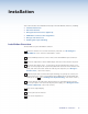
Installation This section describes the installation and setup of the SW HDMI LC switchers, including: zz Installation Overview zz Rear Panel Features zz Wiring the Power Connector (Optional) zz HDMI Video Connectors Pin Assignments zz Wiring for RS-232 Control zz Enabling Auto-input Switching Installation Overview To install and set up the SW HDMI LC switcher: 1 Mount the switcher on a rack shelf or furniture, if desired. See “Mounting the SW HDMI LC” in the “Reference Information” section.
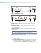
Rear Panel Features SW2 HDMI LC OUTPUT INPUTS POWER 12V 0.5A MAX REMOTE/AUTO-SW 2 1 Tx Rx 1 2 A S 4 3 Figure 2. SW2 HDMI LC Rear Panel SW4 HDMI LC OUTPUT INPUTS POWER 12V 0.5A MAX 1 2 3 REMOTE/AUTO-SW 4 Tx Rx 1 2 3 A S 4 Figure 3. SW4 HDMI LC Rear Panel a Power connector — Plug the provided external 12 VDC power supply into this 2-pole, 3.5 mm captive screw connector. b Video input connectors — Connect HDMI video input sources to these Type A female single-link HDMI connectors.
Wiring the Power Connector (Optional) A 12 VDC, 1 A desktop power supply with a 2-pin captive screw connector attached is provided with the SW HDMI LC. If you are using a different external power supply from the provided one, you may need to wire the captive screw connector for your power supply. CAUTIONS: The power supply must not be permanently fixed to the building structure or similar structures. The power supply must not be located within environmental air handling spaces or the wall cavity.
5. Use the supplied tie-wrap to strap the power cord to the extended tail of the connector. The figure below shows how to wire the connector. 7/8” (22 mm) Heat Shrink 1/8” (3 mm) 3/16” (5 mm) Max. Tie Wrap Captive Screw Connector Figure 4. Power Connector Wiring HDMI Video Connector Pin Assignments The pin assignments for the video connectors are shown in the table below. NOTE: Appropriate HDMI to DVI cables or adapters are required for DVI signal input and output.
Wiring for RS-232 Control The 5-pin, 3.5 mm Remote/Auto-SW captive screw connector is used for optional RS-232 communication, such as firmware updates, and to enable auto-input switching between inputs connected to the switcher. Use a female 9-pin, D to bare wire RS-232 cable or a universal control cable (UC 50', UC 100', or UC 200') to connect your computer or control system to the RS-232/Auto-SW connector.
Enabling Auto-input Switching You can set up the SW HDMI LC to automatically select the active, connected input based on detection of an active video signal. If two or more inputs are active, the input with the highest number is selected (for example, input 4 on an SW4 HDMI LC switcher). When auto-input switching is in effect, the green Auto Switch LED on the front panel lights and the front panel input selection buttons are disabled. To enable auto-input switching, 1.
Operation This section describes the operation of the SW HDMI LC switchers, including: zz Front Panel Features zz Operations Front Panel Features 1 2 AUTO SWITCH IR 3 1 2 SIGNAL ACTIVE 1 2 SW2 HDMI LC HDMI SWITCHER 4 Figure 8. SW2 HDMI LC Front Panel 1 2 AUTO SWITCH IR 3 1 2 3 4 SIGNAL ACTIVE 1 2 3 4 SW4 HDMI LC HDMI SWITCHER 4 Figure 9. SW4 HDMI LC Front Panel a Auto Switch LED — This LED lights when auto-input switching is in effect.
c Input Selection buttons and LEDs — Press these buttons to select inputs 1 and 2 or 1 through 4, depending on your model. The LED at the right of each button lights when the corresponding input is selected. (These buttons are disabled if autoinput switching is in effect; however, the LEDs continue to light to indicate the input selection.
Using the Optional IR 102 Remote Control The optional hand-held IR 102 Remote Control (part #70-224-10) lets you remotely perform functions that are also available through the front panel buttons and SIS commands. The IR receiver port on the front panel is located to the right of the Auto Switch LED.
Enabling Front Panel Lockout (Executive Mode) Executive mode disables all front panel controls, locking out the user from those functions. Putting the switcher in this mode enhances security by protecting against inappropriate or accidental changes to settings. When the switcher is in executive mode, RS-232 and IR control remain available. To lock or unlock the front panel: 1. Press and hold Input buttons 1 and 2 simultaneously. 2.
Remote Communication and Control This section describes remote control operation of the SW HDMI LC switchers, including: zz Using Simple Instruction Set (SIS) Commands zz Updating Firmware Using Firmware Loader Using Simple Instruction Set (SIS) Commands The SW HDMI LC can be remotely set up and controlled via a host computer or other device (such as a control system), attached to the rear panel Remote/Auto-SW port, using the Extron Simple Instruction Set (SIS) commands.
Error Responses If the switcher is unable to execute a command it receives because the command is invalid or contains invalid parameters, the switcher returns an error response to the host.
Command/response Table for SIS Commands ASCII Command Response (host to unit) (unit to host) X! ! In X! • All ] Select input X!. X! = input number 0 through highest number of inputs on the switcher. For X!: 0 = deselect all inputs Adjust EQ level for an individual input E X! * X@ ISEQ } X! ISEQ • X@ ] Adjust the equalization level for input X! to X@.
Command/response Table for SIS commands, Continued Command ASCII Command Response (host to unit) (unit to host) Additional Description Request information, part number, and firmware version (continued) Request part number N 60-xxxx-01 ] Show the switcher part number: SW2 HDMI LC: 60-1159-01 SW4 HDMI LC: 60-1160-01 Query firmware version Q X% ] Show the current firmware build number X%, expressed to the second decimal place. Example: Q 1.
Updating Firmware Using Firmware Loader Updates to the SW HDMI LC firmware are made available periodically via the Extron Web site. You can find out what version of firmware is currently loaded on your switcher by entering the SIS “Q” command via the RS-232 interface. See “Using Simple Instruction Set (SIS) Commands,” earlier in this section, for the procedure for entering SIS commands.
2. On the next Download Center screen, click the SW HDMI LC Download link. 3. On the next screen that appears, enter the requested user information, then click the Download button. 4. Follow the instructions on the rest of the download screens to save the executable firmware file to your computer. Note the folder to which you saved the file. 5. In Windows Explorer or another file browser, locate the downloaded executable file, and double-click it to open it. 6.
Figure 15. Add Device Window NOTE: Although the screen also has a TCP/IP tab, the SW HDMI LC does not have a LAN port. Do not select the TCP/IP tab. 5. Click Connect. Your switcher name is added to the Connected Devices field in Firmware Loader window. 6. In the New Firmware File (Optional) section, click Browse. 7. In the Open window, locate the firmware file to be uploaded to your switcher and double-click on its name. The file extension must be .S19.
8. Click Add to add your switcher name to the Firmware Loader screen. The Add Device window closes, leaving the Firmware Loader window open with your SW HDMI LC name highlighted and selected in the Devices field. Figure 17. Firmware Loader Screen with an SW HDMI LC Added or Click Add Next if you want to upload firmware to multiple Extron devices at the same time (they do not all have to be SW HDMI LC switchers). Your switcher is added to the Firmware Loader screen and the Add Device window remains open.
Figure 18. Firmware Upload in Progress 10. When the firmware update is finished, “Completed” appears above the progress bar, the Progress field displays “100%,” and the Status field displays “Completed.” Close the Firmware Loader window. Removing a device from the Firmware Loader To delete a device from the Devices section of the Firmware Loader window without uploading firmware to it: 1. In the Devices field, click on the name of each device to be deleted, to highlight it.
Reference Information This section reference information for the SW HDMI LC switchers. Topics that are covered include: zz Specifications zz Part Numbers zz Mounting the SW HDMI LC Specifications NOTE: *Appropriate HDMI to DVI-D cables or adapters are required for DVI signal input/output.
General External power supply �������������� 100 VAC to 240 VAC, 50-60 Hz, external; to 12 VDC, 1 A, regulated Power input requirements ��������� 12 VDC, 0.5 A Temperature/humidity ��������������� Storage: -40 to +158 °F (-40 to +70 °C) / 10% to 90%, noncondensing Operating: +32 to +122 °F (0 to +50 °C) / 10% to 90%, noncondensing Cooling ������������������������������������ Convection, no vents Thermal dissipation 115 VAC, 60 Hz ������������������ 4.6 BTU/hr 240 VAC, 50 Hz ������������������ 5.
Part Numbers Included Parts These items are included with SW HDMI LC switcher: Included Parts Replacement Part Numbers SW2 HDMI LC SW4 HDMI LC 60-1159-01 60-1160-01 12 VDC, 1 A external power supply with captive screw connector 70-775-01 IEC power cord 3.
Mounting the SW HDMI LC The SW HDMI LC switcher can be set on a table, mounted on a rack shelf, or mounted under a desk, podium, or table. Tabletop Use Four self-adhesive rubber feet are included with the SW HDMI LC. For tabletop use, attach one foot at each corner on the bottom of the unit and place the switcher where desired. Rack Mounting UL rack mounting guidelines The following Underwriters Laboratories (UL) guidelines pertain to the safe installation of the equipment in a rack. 1.
4. Install the shelf in the rack. 1U Universal Rack Shelf 1/2 Rack Width Front False Faceplate Front false faceplate uses 2 screws. Use 2 mounting holes on opposite corners. (2) 4-40 x 3/16" Screws Figure 19. Mounting an SW HDMI LC Switcher on a Standard 9.5-inch Deep Rack Shelf Mounting to the back of the rack The SW HDMI LC can also be mounted vertically to the front or rear rack supports, using the optional MBB 100 Back of the Rack Mounting Kit (part #70-367-01) as follows: 1.
4. Mount the switcher to the rack support, using the two included rack screws. IR 1 2 3 4 IN PU TS 5 6 7 8 1 2 3 OU 4 TP UT S 5 6 7 8 EN TE R PR ES ET AV VID AU D MAV MA TR SE I/O IX SW RIE ITC S HE R +d B -d B AU DIO SE TU P Figure 21. Mounting an SW HDMI LC Switcher to a Back of the Rack Support Furniture Mounting To mount an SW HDMI LC switcher under a desk, table, or podium, use the optional MBU 123 Mini Under-Desk Mounting Kit (part #70-212-01) as follows: 1.
6. Insert #8 wood screws into the four pilot holes. Tighten each screw into the mounting surface until slightly less than 1/4 inch of the screw head protrudes. 7. Align the centers of the slots in the brackets with the mounting screws and place the unit against the surface, with the screw heads through the bracket slots. 8. Slide the unit slightly forward or back, then tighten all four screws to secure it in place.
Extron Warranty Extron Electronics warrants this product against defects in materials and workmanship for a period of three years from the date of purchase.
Extron USA - West Headquarters +800.633.9876 Inside USA / Canada Only +1.714.491.1500 +1.714.491.1517 FAX Extron USA - East Extron Europe Extron Asia Extron Japan Extron China Extron Middle East +800.633.9876 +800.3987.6673 +800.7339.8766 +81.3.3511.7655 +81.3.3511.7656 FAX +400.883.1568 +971.4.2991800 +971.4.2991880 FAX +1.919.863.1794 +1.919.863.1797 FAX +31.33.453.4040 +31.33.453.4050 FAX +65.6383.4400 +65.6383.