
User Guide Manual

SMX System MultiMatrix Switcher • SIS Configuration and Control 46
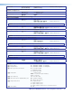
Command ASCII Command
(Host to switcher)
Response
(Switcher to host)
Additional Description
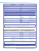
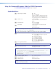
Query system status
S
X2$
•
X2$
•
X2$
•
X2%
•
X2^
•
X2^
•
X3#
•
X3$]
Query specific system status
nS
X2$ or X2% or X2^ or X3#]
Stsn*X2$ or X2% or X2^ or X3#] Verbose mode 2 or 3
Example:
S
Sts0* 3.31 4.98 24.22 +100.40 03305 03308 1 0
]
3.31 and 4.98 are power supply voltages; 24.22 is fan voltage,
100.40 (degrees F) is the temperature, 03305 is fan 1 rpm, 03308
is fan 2 rpm, 1 is primary power supply (OK).
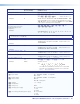
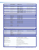
Query switcher information
(general) per plane (16 actual
and 10 virtual) plus board
configuration
I
V
X@
0
XX#
0
AX@
0
XX#
0
•
...VX@
15
XX#
15
AX@
15
XX#
15
•
...
VX@
25
XX#
25
AX@
25
XX#
25
]
Example:
V16x16A16x16
•
V--X--A--X--
•
V--X--A--X--
•
V--X--A-
-X--
•
... ...
•
V--X--A--X--]
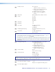
NOTE: The I response gives 26 parameters, the first 16 (V_x_A_x_) is plane information (planes 0-15), and the next
are virtual planes 1-10 (90-99).
Query model name
Example:
1I
Switcher description (short)
]
Inf01*Switcher description (short)] Verbose mode 2 or 3
Inf01*SMX]
Query model description
Example:
2I
Switcher description (long)
]
Inf02*Switcher description (long)] Verbose mode 2 or 3
Inf02*System Multi Matrix]
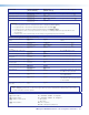
Query system-memory usage
3I
# of Bytes used out of # KBytes
]
Inf03*# of Bytes used out of # KBytes Verbose mode 2 or 3
Query user-memory usage
4I
# of Bytes used out of # KBytes
]
Inf04*# of Bytes used out of # KBytes Verbose mode 2 or 3
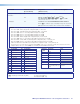
Query plane address per slot
ESTAT}
X2@
(slot 1)
•X2@
(slot 2)
•...X2@
(
slot 6/8/10)
] Verbose mode 2 and 3
StatX2@
(slot 1)
•X2@
(slot 2)
•...X2@
(slot 6/8/10)
]
Example:
Stat*
5U frame, 10 slots
Slot 1
2 3 4 5 6 7 8 9 10
00
•
01
•
--
•
02
•
--
•
--
•
03
•
--
•
03
•
03]
Slot 1 00 the board address installed in slot 1 is plane 00
Slot 2 01 the board address installed in slot 2 is plane 01
Slot 3 - - No board installed
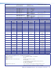
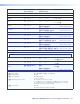
NOTES:
X@ = Input number 01 - <maximum number of inputs>
00 = untied
X# = Output number 01 - <maximum number of outputs>
X2@ = Plane number 00 - 15
90 - 99 = virtual plane
X2$ = Voltage + or – voltage
X2% = Temperature
X2^ = Fan speed RPM
X3# = Primary power supply 0 = not installed
1 = OK
2 = failed
X3$ = Secondary (redundant) power supply 0 = not installed
1 = OK
2 = failed