
User Guide Manual

SMX System MultiMatrix Switcher • Installation and Cabling 8
Reset button and Ethernet cable termination
It is essential that the Ethernet cables used be the correct type of cable and terminated with
the correct pinout. The cable can be terminated as either a patch cable or a crossover cable
and must be properly terminated relevant to the application (see Ethernet Control on
page 106 for termination details).
c
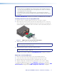
Reset button (recessed) — Press and hold in this recessed button to reset the
SMX to the default (factory setting) mode. The lit (green) LED blinks once.
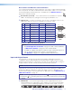
d
Remote port — Connect a host device, such as a PC or touchpanel control, to the
SMX via this 9-pin D connector for serial RS-232 or RS-422 control.
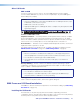
Pin RS-232 Function RS-422 Function
1 — Not used — Not used
2 Tx Transmit data Tx Transmit data (-)
3 Rx Receive data Rx Receive data (-)
4 — Not used — Not used
5 Gnd Signal ground Gnd Signal ground
6 — Not used — Not used
7 — Not used Rx+ Receive data (+)
8 — Not used Tx+ Transmit data (+)
9 — Not used — Not used
Figure 3. Remote Port Pin Assignments
NOTES:
• See SIS Configuration and Control on page 34 for SIS command definitions
or SMX Control Software on page 59 control software details.
• The SMX can support either RS-232 or RS-422 serial communication protocol,
and can operate at 9600, 19200, 38400, or 115200 baud rates
(see Operation on page 13 to configure the RS-232/RS-422 port).
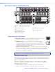
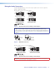
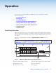
Input and Output Boards
The I/O boards on any unit may vary with each installation, depending on desired
configuration and use. All board types have the input and the output connectors clearly
marked, and each board has a 16-position rotary switcher (see m, figure 2) for setting the
I/O plane address. An LED on the board indicates when power is present.
NOTE: Boards with the same plane address switch simultaneously.
Figure 2 shows some, but not all, board variations that can be installed into an SMX frame.
Boards have different combinations of input and output connectors, depending on the
specific board installed. To install any board into an SMX frame slot (see SMX Frame and
I/O Board Installation on page 10).
NOTE: Control signal ground pins may be labeled as or “G”. Audio ground pins may
be labeled as or . The wiring and function are the same, whichever way your product
is labeled.
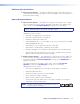
e SMX 44 DVI — Connect DVI single link high resolution digital input devices (up to
1600x1200 @ 60 Hz) or HDTV devices up to 1080p, to any of the DVI-I female input
connectors. Connect suitable digital displays to the DVI-I female output connectors.
DVI-D INPUTS
1
2
3
4
DVI-D OUTPUTS
1
2
3
4
ADDRESS
RS-232 FunctionPin
1
2
3
4
5
6
7
8
9
—
TX
RX
—
Gnd
—
—
—
—
Not used
Transmit data
Receive data
Not used
Signal ground
Not used
Not used
Not used
Not used
51
9
5
9
6
Female
Male
1
6
RS-422 Function
TX
RX
—
Gnd
—
RX+
TX+
—
Not used
Transmit data (-)
Receive data (-)
Not used
Signal ground
Not used
Receive data (+)
Transmit data (+)
Not used
—
RESET