
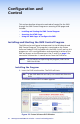
Setup Guide

26 SMX System MultiMatrix Switcher • SIS Programming Guide
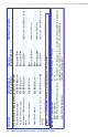
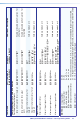
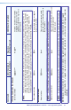
Command ASCII Command
(host to switcher)
Response
(switcher to host)
Additional Description
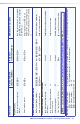
Information Requests
NOTE: Firmware version, part number, and information are for the primary frame only.
Query firmware version
Q
X2!]
Example:
Q
1.14]
Ver01*
X2!
] Verbose mode 2 or 3
Query system status
S
X2$
•
X2$
•
X2$
•
X2%
•
X2^
•
X7&
•
X7*]
Example:
S
Sts0*3.31 4.98 24.22 +100.40 03305 03308 1 0]
(Verbose mode 2 or 3)
3.31 and 4.98 are power supply voltages; 24.22 is fan voltage,
100.40 (degrees F) is temperature, 03305 is fan 1 rpm, 03308 is fan 2
rpm, 1 is primary power supply (OK).
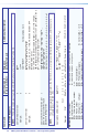
Query Switcher Information per
plane (16 actual and 10 virtual)
plus board configuration
I
V
X@
0
X
X#
0
A
X@
0
X
X#
0
•
...V
X@
15
X
X#
15
A
X@
15
X
X#
15
•
...
V
X@
25
X
X#
25
A
X@
25
X
X#
25
]
V16x16A16x16
•
V--X--A--X--
•
V--X--A--X--
•
V--X--A--X--
•
...V--X--A--X--]
NOTE: The I response gives 26 parameters, the first 16 (V_x_A_x_) are plane information (planes 0-15), and the next are
virtual planes 1 - 10 (90 - 99).
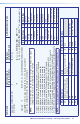
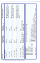
Query plane address per slot
ESTAT}
X2@
(slot 1)
•
X2@
(slot 2)
•...
X2@
(slot 6/8/10)
]
Stat
X2@
(slot 1)
•
X2@
(slot 2)
•...
X2@
(slot 6/8/10)
]
Slot 1 2 3 4 5 6 7 8 9 10
Example: Stat* 00
•
01
•
--
•
02
•
--
•
--
•
03
•
--
•
03
•
03]
(5U frame, 10 slots)
-- indicates no board is installed
NOTES: X@ = Input number 01 - <maximum number of inputs>, 00 = untied
X# = Output number 01 - <maximum number of outputs>
X2! = Firmware version number x.xx
X2@ = Plane number X2^ = Fan speed (rpm)
X2$ = Voltage (+ or - voltage)
X7& = Primary power supply 0 = not installed, 1 = OK
X2% = Temperature
X7* = Secondary (redundant) power supply 0 = not installed, 1 = OK