Setup Guide Matrix Switcher SMX System MultiMatrix Switcher 68-1452-50 Rev.
Safety Instructions • English This symbol is intended to alert the user of important operating and maintenance (servicing) instructions in the literature provided with the equipment. This symbol is intended to alert the user of the presence of uninsulated dangerous voltage within the product’s enclosure that may present a risk of electric shock. Caution Read Instructions • Read and understand all safety and operating instructions before using the equipment.
FCC Class A Notice This equipment has been tested and found to comply with the limits for a Class A digital device, pursuant to part 15 of the FCC Rules. Operation is subject to the following two conditions: 1. This device may not cause harmful interference. 2. This device must accept any interference received, including interference that may cause undesired operation.
Conventions Used in this Guide In this user guide, the following are used: NOTE: TIP: A note draws attention to important information. A tip provides a suggestion to make working with the application easier. CAUTION: A caution indicates a potential hazard to equipment or data. WARNING: A warning warns of things or actions that might cause injury, death, or other severe consequences.
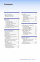
Contents Introduction........................................1 SIS Programming Guide.................19 About This Guide................................1 About the SMX System MultiMatrix Switcher........................1 SIS Overview......................................19 Network (Ethernet) Connections.................................19 Verbose Mode...............................20 Host-to-switcher Instructions.......20 Error Messages..............................20 EDID................................
vi SMX System MultiMatrix Switcher • Contents
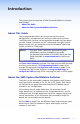
Introduction This section gives an overview of SMX System MultiMatrix switchers and includes: •• About This Guide •• About the SMX System MultiMatrix Switchers About This Guide This setup guide describes basic instructions for the set up, configuration, and operation of the Extron SMX matrix switcher.
FOX HDSDI POWER 12V 0.3A MAX OPTICAL MODE HD/SDI IN 1 1 2 Tx 2 BUFFERED OUTPUTS Rx Extron FOX HD-SDI Transceiver FOX HDSDI POWER 12V 0.
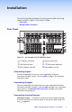
Installation This section provides procedures for setting up the SMX and wiring audio connectors.
The Ethernet connection indicator LEDs marked "Link" and "Act" indicate the status of the SMX Ethernet connection. The Link LED lights green when connected to an Ethernet LAN, and the Act LED flickers amber, as the devices communicate. NOTE: Do not use standard telephone cables, as they do not support Ethernet or fast Ethernet. Do not stretch or bend cables as transmission errors could occur.
L L R Tip Ring Sleeve R Tip Ring Sleeves Tip Ring Balanced Stereo Input Balanced Mono Input (high impedance) L L Tip Sleeve R Tip Sleeve Tip Sleeve R Unbalanced Stereo Input Unbalanced Mono Input Figure 3. Audio Input Captive Screw Wiring NOTES: • A mono audio connector consists of the tip and sleeve, whereas a stereo audio connector consists of the tip, ring, and sleeve. The tip, ring, and sleeve wires are also shown in figure 4 (balanced inputs).
Front Panel Operation This section details the physical configuration and front panel operation of the SMX after the installation process and includes: •• Front Panel Overview •• Creating Ties •• Viewing Ties •• Muting or Unmuting Outputs •• Removing Ties •• Saving and Recalling I/O Presets •• Adjusting the Input Audio Level •• Adjusting the Output Audio Volume •• Using Reset Levels •• Setting the Front Panel Locks (Executive Modes) Front Panel Overview 1 4 I/O PLANE SELECT 0 1 2 3 4
e Power status LEDs — Indicate power status for the main unit and I/O boards. f Front panel configuration port — Connects a control system or computer to this (RS-232) port, using an optional 9-pin D to 2.5 mm mini jack TRS RS-232 cable, part number 70-335-01. RS-232 protocol (default values): • 9600 baud • 1 stop bit • no parity • 8 data bits • no flow control NOTE: Unless specified otherwise, buttons on the SMX light green for video boards, red for audio boards, and amber for audio and video boards.
Viewing Ties 1. Press the Esc button to clear any pending changes. The button flashes once. 2. Press the View button. The last selected Plane button and untied, unmuted buttons light. Untied and muted buttons flash. C O NT R O L ENTER PRESET VIEW ESC 3. Press the I/O Plane button that corresponds to the plane address of the desired I/O board. Buttons light as specified in step 2.
4. Perform one of the following: •• To mute outputs, press and hold lit or unlit output buttons for 2 seconds. •• To unmute outputs, press and hold flashing output buttons for 2 seconds. INPUTS 1 2 3 4 5 6 7 8 9 10 11 12 13 14 15 16 1 2 3 4 5 6 7 8 9 10 11 12 13 14 15 16 OUTPUTS Figure 12. Unmuted Outputs 2, 5, and 8 and Muted Outputs 6, 9, 10, and 16 — an Example NOTE: For video, only RGB is muted. Sync is not muted. For RGBHV systems, only the R, G, and B boards are muted.
Saving and Recalling I/O Presets Save current configurations as global or plane presets to save audio and video ties. The SMX has 32 global preset (using I/O buttons 1-16) and 10 plane presets (input buttons 1-10) addresses available. Global preset — Saves and recalls configurations for all planes (see figure 14 for global preset addresses). Plane preset — Saves and recalls the configurations for a specific plane without affecting the other plane connections (see figure 14 for plane preset addresses).
3. Pick a global preset number (see figure 14) and perform one of the following: •• To save a global preset, press the desired input or output button. This overwrites a previously saved global preset. •• To recall a global preset, press the desired lit input or lit output button. INPUTS 1 2 3 4 5 6 7 8 9 10 11 12 13 14 15 16 1 2 3 4 5 6 7 8 9 10 11 12 13 14 15 16 OUTPUTS Figure 16. Global Preset 21 Selected — an Example Upon selection, the button and the Enter button flash red. 4.
Adjusting the Input Audio Level The audio level of each input can be displayed and adjusted through a range of -18 dB to +24 dB. The level can be adjusted from the front panel, RS-232, RS-422, or Ethernet connection. NOTE: Refer to the SMX User Guide for other adjustment methods. 1. Press the Esc button to clear any pending changes. The button flashes green once. 2. Press the desired audio I/O Plane button to be adjusted. The plane button and an Input button light.
Input Audio Level Table dB Color Output Buttons Lit or Flashing +/- dB Color Output Buttons Lit or Flashing +/- 24 green 12 > -01 red 1 flash < 23 green 12 flash > -02 red 1 flash < 22 green 11 > -03 red 2 flash < 21 green 11 flash > -04 red 2 flash < 20 green 10 > -05 red 3 flash < 19 green 10 flash > -06 red 3 flash < 18 green 9 > -07 red 4 flash < 17 green 9 flash > -08 red 4 flash < 16 green 8 > -09 red 5 flash < 15 green
Adjusting the Output Audio Volume The audio output level of each output can be displayed and adjusted through a range of 64 steps (1 dB per step, 0% to 100%). The audio level can be adjusted from the front panel, RS-232, RS-422, or through Ethernet. Adjustment is attenuation only. NOTES: • Refer to the SMX User Guide for other adjustment methods. • Front panel adjustment and viewing are only available when the unit is in Lock mode 0. 1. Press the Esc button to clear any pending changes.
Output Audio Volume Table Volume % dB Attenuation Buttons Lit or Flashing SIS Command Volume % dB Attenuation Buttons Lit or Flashing SIS Command 100 0 16 plane*out# *64V 52.0 32 8 plane*out# *32V 98.5 1 16 63 50.5 33 8 31 97.0 2 slow 62 49.0 34 slow 30 95.5 3 slow 61 47.5 35 slow 29 94.4 4 15 60 46.0 36 7 28 92.5 5 15 59 44.5 37 7 27 91.0 6 slow 58 43.0 38 slow 26 89.5 7 slow 57 41.5 39 slow 25 88.0 8 14 56 40.0 40 6 24 86.
Using Reset Levels The rear panel has a recessed Reset button (see page 3) that initiates four levels of resets (numbered 1, 3, 4, and 5). Use a pointed stylus, ballpoint pen, or Extron Tweeker to access it and select the reset level. See the Reset Mode Table on page 17 for a summary of the modes. CAUTION: NOTES: Review the reset modes carefully. Using the wrong reset mode may result in unintended loss of flash memory programming, port reassignment, or a controller reboot.
Reset Mode Table Mode Action Result 1 Hold down the recessed Reset button while applying power to the switcher. Defaults switcher to factory installed firmware. Event scripting will not start if the switcher is powered on in this mode. All user files and settings (drivers, adjustments, IP settings, and so on) are maintained (see notes below). 3 Hold down the Reset button for 3 seconds, until the Reset LED blinks once, then press Reset momentarily (<1 second) within 1 second.
Setting the Front Panel Locks (Executive Modes) The SMX has three levels of front panel security lock. Lock mode 0 — The front panel is completely unlocked and all basic and advanced features are available. Lock mode 1 (Executive mode) — All changes are locked from the front panel (except for View mode and setting Lock mode 2). Lock mode 2 (Advanced Executive mode) — Basic functions are unlocked. Advanced features are locked and can be viewed only (default mode).
SIS Programming Guide The SMX uses SIS commands for operation and configuration. These commands can be run from a PC connected to either of the SMX serial ports or the Ethernet port. See b and d on page 3, and f on page 7 for connection information. NOTE: The tables that begin on page 22 are a partial list of SIS commands (see the SMX User Guide for a complete list).
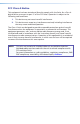
Number of connections An SMX can have up to 200 simultaneous TCP connections, including all HTTP sockets and Telnet connections. When the limit is reached, the SMX accepts no new connections until some have been closed. No error message or indication is given that the limit has been reached. To maximize performance unnecessary open sockets should be closed. Verbose Mode Telnet connections can be used to monitor changes that occur on the SMX. The Telnet session must be in verbose mode 1 or 3.
EDID — Extended Display Identification Data A communications protocol or instruction set for the identification of display devices to computers using the DDC (Display Data Channel) transmission standard (see page 28 for SIS commands).
22 SMX System MultiMatrix Switcher • SIS Programming Guide ASCII Command (host to switcher) Response (switcher to host) Additional Description X2@ Out X# •In X@ • Vid] X2@ Out X# •In X@ • Aud] X2@ Out X# •In X@ • All] X2@*X@*X# % X2@*X@*X# $ X2@*X@*X# ! Tie input to an output (video) Tie input to an output (audio) Tie input to an output (all) Tie input X@ to output X# on plane X2@ for all signals. Tie input X@ to output X# on plane X2@ for audio signals.
SMX System MultiMatrix Switcher • SIS Programming Guide 23 Qik] E+Q01*3*4!01*3*5%... 01*3*6$} X@] X2@*X# $ View audio output tie X(] X2@ Vmt00*1] X2@ Vmt00*0] X2@*X# B X2@*1*B X2@*0*B Read RGB mute RGB/video mute per plane RGB/video unmute per plane 01 - , 00 = untied 01 - X2@ Vmt X#*0] X2@*X#*0B RGB/video unmute NOTES: X@ = Input number X# = Output number X2@ Vmt X#*1] X2@*X#*1B Unmute RGB/video plane. Mute RGB/video plane.
24 SMX System MultiMatrix Switcher • SIS Programming Guide X2@ Amt00*1] X2@ Amt00*0] X2@*1*Z X2@*0*Z Audio mute entire plane Audio unmute entire plane Save current tie set as preset 9. Recall global preset X1!, and becomes the current configuration. Command character is a period (.). Recall preset 5 as current configuration. Spr09] Rpr X1!] Rpr05] 9, X1!. 5.
SMX System MultiMatrix Switcher • SIS Programming Guide 25 X2@ Rpr X1!] X2@*X1!*0. Recall a plane preset X2@1,X2@ 2,...X2@ n] E X2( MP} Read virtual plane address Disable executive mode. X( = status of executive mode.
26 SMX System MultiMatrix Switcher • SIS Programming Guide Response (switcher to host) X2!] 1.14] Ver01*X2!] X2$ • X2$ • X2$ • X2% • X2^ • X7& • X7*] Sts0*3.31 4.98 24.22 +100.40 03305 03308 1 0] (Verbose mode 2 or 3) 3.31 and 4.98 are power supply voltages; 24.22 is fan voltage, 100.40 (degrees F) is temperature, 03305 is fan 1 rpm, 03308 is fan 2 rpm, 1 is primary power supply (OK). V X@ 0 X X# 0 A X@ 0 X X# 0 •...V X@ 15 X X# 15 A X@ 15 X X# 15 •...
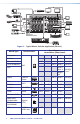
SMX System MultiMatrix Switcher • SIS Programming Guide 27 *N For all combinations, see the tables to the right and below. The upper table gives the X value. Lower table gives the YZ value. NOTE: Board Size No board installed or slot covered by multi slot board 4x4 4x8 8x4 (YZ) 00 04 05 06 For sync and S-video For S-video BNC Refer to next slot for size of board Note Only slots labeled X00 are open and available for additional boards.
28 SMX System MultiMatrix Switcher • SIS Programming Guide ASCII Command (host to switcher) X3) EdidS X3@] X3@] X3) EdidA X!*X3@ ] X6) ] X3) EdidE X3@*X6) ] X3) EdidI X3@ ] E S X3)*X3@ EDID} E A X3)*X! EDID} E E X3)*X3@ EDID} E I X3)*X3@ EDID} X6) Save output 1 EDID data to user space View EDID data assignment Export EDID file data Import EDID file data to user file location 01 - 01 -10 00 - 40, where 15 = default, 1 - 8 = stored from connected EDID monitors as referen
SMX System MultiMatrix Switcher • SIS Programming Guide 29 ASCII Command (host to switcher) X( X( X( ...X( ] X3) UsbcE*X( 1 X( 2...X( n] X3) = Slot number NOTES: X! = Input number X# = Output number X( = Emulation status X1@ = Input connection status X2) = Output connection status X2) X2) X2) ... X2) ] X3) UsbcO*X2) 1 X2) 2 X2) 3...
30 SMX System MultiMatrix Switcher • SIS Programming Guide Ips• X1(] X1(] Ipg • X3%] X3%] X3) Ipe X4# *X4!*X4$*X4%] X4%X4%X4%... X4%] EX1( CS} E CS} EX3% CG} E CG} EX4#X4!,X3),X4$,X4% EM} EX4#X4!,X3),X4$ EM} Set subnet mask View subnet mask Set gateway IP address View gateway IP address Set E-mail events for recipient View E-mail events for recipient X4% = Notify when? format ###.###.###.###. Leading zeros in all the four fields are optional. X3% = gateway IP address in the ###.###.###.
SMX System MultiMatrix Switcher • SIS Programming Guide 31 Enable or disable verbose mode or tagged responses, in which additional information is given in query response. Additional Description E ZXXX} E CV} Zpx] X3&] Clears all ties and presets, audio gain and volume, and resets unit to factory default. Show verbose mode or tagged response status X3&. E ZQQQ} Zpq] Clears all ties and presets, and resets unit to factory default (mode 5 reset).
Configuration and Control This section describes alternative methods of control for the SMX through the SMX Control Program or accessing HTML pages and includes: •• Installing and Starting the SMX Control Program •• Accessing the HTML Pages •• Using the Web Pages to Configure the SMX Installing and Starting the SMX Control Program The SMX can be configured and operated via the Windows-based SMX Control Program. This program is contained on the Extron Software Products DVD (included with the SMX).
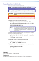
2. Click the Software tab. 3. Scroll to the SMX Control Program and click Install. 4. Follow the on-screen instructions. The installation program creates a C:\Program Files\Extron\SMX folder with 3 icons for the SMX Control pgm, SMX Help, and Uninstall SMX Control pgm. Starting the Program 1. Click Start > Programs > Extron Electronics > SMX Control Program > SMX Control Pgm. The Comm Port Selection window appears. Figure 24. Comm Port Selection Window 2.
a. Examine the Matrix IP Address field, which displays the last Matrix IP address entered and a drop-down list with a list of the most recently used IP addresses. If listed, select the applicable IP address, or enter the correct IP address in the field. NOTE: The default IP address is 192.168.254.254. b. If the SMX is password-protected, enter the appropriate administrator or user password in the Password field. c. Click Connect. The SMX Control Program is ready for operation.
Using the Web Pages to Configure the SMX The SMX settings can be configured via LAN or WAN web pages using a suitable Internet browser (Internet Explorer, Firefox®). To view and configure the SMX via web pages: 1. If not already done, connect the SMX to a PC using the rear panel RJ-45 LAN connector. 2. Open the Internet browser on the host computer, and in the address bar, type the IP address for the SMX . NOTE: The default IP address is 192.168.254.254.
Configuration Page This page sets system, e-mail, and password settings and upgrades Firmware. Subsections include System Settings, Passwords, Email Settings, and Firmware Upgrade. File Management Page This page allows files to be uploaded and deleted from the SMX. Control Page The User Control section allows, for each plane, the input to output ties to be set and viewed, the input audio gain and attenuation to be adjusted, and output audio volume settings to be changed.
Reference Material This section describes Ethernet links, connector wiring, mounting methods, and board installation. Topics in this section includes: •• Ethernet Link •• Mounting the SMX •• Installing New Boards Ethernet Link The rear panel Ethernet connector on the SMX can be connected to an Ethernet LAN or WAN. This connection allows for SIS control using a computer connected to the same LAN.
Mounting the SMX Use two screws on each side of the SMX to attach the front panel to a rack. See the SMX User Guide for other mounting considerations (www.extron.com). Installing New Boards NOTE: All boards are hot-swappable, and can be installed without shutting down the SMX or removing the power. 1. Take note of how many slots your board needs to occupy. a. If necessary, remove as many blank panels as needed. b.
Notes: SMX System MultiMatrix Switcher • Reference Material 39
40 SMX System MultiMatrix Switcher • Reference Material
Extron® Warranty Extron Electronics warrants this product against defects in materials and workmanship for a period of three years from the date of purchase.
Extron USA - West - Headquarters Extron USA - East Extron Europe Extron Asia Extron Japan Extron China +800.633.9876 Inside USA/Canada Only +800.633.9876 Inside USA/Canada Only +800.3987.6673 Inside Europe Only +800.7339.8766 Inside Asia Only +81.3.3511.7655 +81.3.3511.7656 FAX +400.883.1568 Inside China Only +1.714.491.1500 +1.714.491.1517 FAX +1.919.863.1794 +1.919.863.1797 FAX +31.33.453.4040 +31.33.453.4050 FAX +65.6383.4400 +65.6383.4664 FAX +86.21.3760.1568 +86.21.3760.