User Guide SCP 226 and SCP 104 Series System Control Panels 68-959-01 Rev.
Precautions Safety Instructions • English This symbol is intended to alert the user of important operating and maintenance (servicing) instructions in the literature provided with the equipment. This symbol is intended to alert the user of the presence of uninsulated dangerous voltage within the product’s enclosure that may present a risk of electric shock. Caution Read Instructions • Read and understand all safety and operating instructions before using the equipment.
安全须知 • 中文 警告 这个符号提示用户该设备用户手册中 有重要的操作和维护说明。 电源 • 该 设 备 只 能 使 用 产 品 上 标 明 的 电 源 。 设 备 必须使用有地线的供电系统供电。 第三条线 (地线)是安全设施,不能不用或跳过。 这个符号警告用户该设备机壳内有暴 拔掉电源 • 为安全地从设备拔掉电源,请拔掉所有设备后 或桌面电源的电源线,或任何接到市电系统的电源线。 露的危险电压,有触电危险。 电源线保护 • 妥善布线, 避免被踩踏,或重物挤压。 注意 阅读说明书 • 用 户 使 用 该 设 备 前 必 须 阅 读 并 理 解所有安全和使用说明。 保存说明书 • 用户应保存安全说明书以备将来使 用。 遵守警告 • 用户应遵守产品和用户指南上的所有安 全和操作说明。 维护 • 所有维修必须由认证的维修人员进行。 设备内部没 有用户可以更换的零件。为避免出现触电危险不要自己 试图打开设备盖子维修该设备。 通风孔 • 有些设备机壳上有通风槽或孔,它们是用来防止 机内敏感元件过热。 不要用任何东西挡住通风孔。 锂电池 • 不正确的更换电池会有爆炸的危险。 必须使用与 厂家推荐的相同
Conventions Used in this Guide Notifications the following are used: WARNING: Risk of physical injury. A warning indicates a situation that has the potential to result in death or severe injury. ATTENTION: Attention indicates a situation that may damage or destroy the product or associated equipment. NOTE: A note draws attention to important information. Copyright © 2012 Extron Electronics. All rights reserved.
Contents Introduction ........................................1 Remote Communication ................31 About this Guide .................................1 About the SCP 104 and SCP 226 System Control Panels .......................1 Features ...........................................2 Application Diagrams .........................3 Setting Up RS-232 Communication ...............................31 Communications Between the Host and the SCP .............................31 SCP-initiated Messages ........
vi SCP 104 and SCP 226 • Contents
Introduction This section gives an overview of the SCP 104 and SCP 226 System Control Panels and describes their features. Topics include: •• About this Guide •• About the SCP 104/226 Series System Control Panels •• Application Diagrams About this Guide This guide discusses how to install, connect, and operate the Extron SCP 104 and SCP 226 System Control Panels. Throughout this guide, the terms “SCP 104/226,” “SCP,” and “control panel” are used interchangeably to refer to these products.
The MediaLink controllers and the System 5 IP each support up to two of the SCP 104/226, the SCP 226 L, or the SCP 104/226 AAP models. The MLC 104/226 and the System 5 IP can each support up to four control modules and one IR Link infrared signal repeater, which can be daisy-chained with the panels. The SCP 226 models can accept signals from the optional IR 402 remote control.
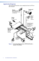
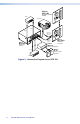
Application Diagrams The following illustrations show examples of how the SCP can be connected.
Extron SCP 104 1 EO 2 X AU O E VID F OF System Control Panel VCR VID AY PL DIS ON 3 PC ME LU VO 4 E AG IM TE MU IG NF CO Projector P SC 4 IP 10 Video Video 1 EO DIS 2 X AU O E VID F OF TP 2 L L 1 R S ML TS PU IN L TS PU R IN 3 DIO L 1 4 R T OU IX X/M AU O MON RS-232 or IR Projector Control OL/ NTR R COOWE P UT OU 3 Extron MLS 103V VID AY PL Audio 3 PC ME LU VO 4 IG NF CO R L A B .
Installation and Operation This section describes the front and rear panel features of the six SCP 104/226 models and provides procedures for installing and operating the control panels.
Installation Overview ATTENTION: Installation and service must be performed by authorized personnel only. To install and set up an SCP control panel: 1. Power off all equipment. Make sure that the SCP and all attached devices are disconnected from the power sources. 2. Set the panel address DIP switch on the back of the SCP (see a "Panel address DIP switches" on page 8). 3. When using two SCPs, set switch 2 as follows: •• Off (down) to set address 1 •• On (up) to set address 2 4.
Fig_Replacing button label Plunger Base TE XT Diffuser Clear Cap 3 Button Label Pry the two pieces apart. 2 Notch Separate the twopiece button here at the corner. Figure 3. Replacing a Button Label 4. Lift out the transparent square label that you want to replace, being careful not to damage the circuits beneath it. You may need to use the small screwdriver to gently pry the label out. 5. Detach one of the preprinted labels or one of the blank labels from the label sheets included with the SCP.
Rear Panel Features and Connections 1 E D C B A E D C B A 1 2 3 4 ON J1 4 2 Figure 4. SCP 104 Rear Panel 4 1 ON J1 E D C B A E D C B A 1 2 3 4 3 2 Figure 5. SCP 226 Rear Panel a Panel address DIP switches — Set these DIP switches as appropriate for your system configuration. •• 8 Switch 1 — Switches the SCP between connected and standalone modes.
NOTE: The SCP must be in standalone mode for communication via SIS commands (see the “Remote Communication” section, beginning on page 31). •• Switch 2 — Sets the addresses for the SCPs ON when two are connected. Ensure that this switch is set to opposite positions on the 1 2 3 4 two SCPs. For example: •• If switch 2 is set to Off (down) on the first SCP, set switch 2 on the second SCP to On (up). •• If switch 2 is set to On (up) on the first SCP, set switch 2 on the second SCP to Off (down).
d Serial port — Use this female 3-pole 3.5 mm captive screw connector to connect the SCP to the serial (RS-232) port on your computer. Through this connection you can enter SIS commands to monitor and obtain information from the SCP (see "Wiring the RS-232 Port" for connection information).
J4 J1 G Ground Rx Receive Tx Transmit Ground (G) 5 Transmit (Tx) 3 Receive (Rx) 2 To Computer or Control System RS-232 Port J6 1 2 3 4 SW12 ON 9-pin HD Connector SCP 226 Rotated Rear Panel Figure 7. Connecting a Host to the SCP 226 2. Plug the 3-pole connector into the RS-232 port on the SCP rear panel. NOTES: • DIP switch #1 must be set to On (up) for the SCP to be able to communicate with the computer or terminal emulator.
Wiring the Power Connector (Optional) If powering the SCP using a 12 V, 1 A external power supply (instead of powering via an MLC or System 5 IP), connect the power supply to ports A and B of either 5-pole captive screw connector on the SCP rear panel. Connect the + wire to port A and the ground wire to port B, as shown in the figures below. Smooth A G G G A B A Ridges SECTION A–A G 3/16” (5 mm) Max. Power Supply Output Cord E D C B A E D C B A Figure 8.
Connecting to the MLC 104/226, the System 5 IP, and Control Modules The diagrams on the following pages illustrate how to connect the SCP to the MLC 104, MLC 226, control modules such as IRCMs or RCMs, and the System 5 IP system switcher. NOTES: • When an SCP 104 is connected to an MLC 104 IP Plus, the SCP must have firmware version 1.01 or higher. • When an SCP 104/226 is connected to a System 5 IP switcher, the SCP must have firmware version 1.
SCP 226 to MLC 226 IP CM/IR/SCP +12V OUT GROUND CONT MOD IR IN SCP COM A B C D E MLC 226 IP Rear Panel DISPLAY ON E SCP Communication OFF PIC MUTE VCR VOLUME AUTO IMAGE B Ground ( ) & Drain Wire A +12 VDC DVD 1 4 2 5 3 6 PC LAPTOP DOC CAM IR 200' (61 m) max.
SCP 226 to MLC 226 IP with IRCM-DV+ control modules CM/IR/SCP +12V OUT GROUND CONT MOD IR IN SCP COM A B C D E MLC 226 IP Rear Panel IRCM-DV+ Control Module Address 1 and 2 DVD & VCR CONTROL DVD Tx VCR TITLE MENU ENTER TV/VCR E SCP Communication TUNER C IRCM, ACM, RCM B Ground ( ) & Drain Wire A +12 VDC PREV/REW PLAY NEXT/FWD PAUSE STOP 200' (61 m) max.
SCP to system switcher A B C D E +V G CM IRSCP NOTE: Maximum Two SCPs Per System System Switcher Rear Panel DISPLAY ON PC OFF E SCP Communication VOLUME C IRCM, ACM, RCM B Ground ( ) & Drain Wire A +12 VDC 1 DOC CAM CONFIG 2 VCR 3 DVD 4 200' (61 m) max. to Last Device SCP 104 C A NOTE: DIP switch 4 must be in the On (up) position.
Two SCP 226s to system switcher and two control modules A B C D E +V G CM IRSCP NOTE: Maximum Two SCPs Per System System Switcher Rear Panel DISPLAY E SCP Communication ON C IRCM, RCM B Ground ( ) & Drain Wire A +12 VDC OFF PIC MUTE VOLUME AUTO IMAGE 200' (61 m) max.
SCP and System 5 IP Button Functions When an SCP is connected to a System 5 IP switcher, buttons on the SCP initiate functions that are also controlled by equivalent buttons on the switcher. The following diagrams show the buttons on the SCP that are tied to buttons on the System 5 IP.
Mounting the SCP After the system has been cabled and tested, the control panel can be mounted to the wall or furniture. Mounting Options You can mount the SCP 104/226 in an electrical box or surface mounting box (not provided), or you can use a mounting bracket (not provided) to secure it to a wall, podium, table, or other furniture. Extron offers a variety of mounting boxes and brackets that you can purchase for the different SCP 104/226 models.
Fig_Mounting SCP 104_2-gang Extron SCP 104 1 2-gang Wall Box R TO 2 EC OJ PR OFF ON 3 ME 4 LU VO CO NF IG Figure 18. Mounting an SCP 104 in a Two-gang Electrical Box ATTENTION: If you are not installing the SCP into a grounded metal electrical box, make sure that the faceplate is grounded to an earth ground. Mounting to a Lectern (SCP 226 L) The SCP 226 L is designed to be mounted to a lectern.
Front Panel Features The controls on the SCP 104/226 replicate the programmed MLC 104/226 buttons and controls, and most of the System 5 IP front panel controls. All button functions for the MLCs and the System 5 IP are configured via RS-232 or Ethernet.
1 7 7 PROJECTOR ON OFF VOLUME 1 2 3 3 4 7 7 SCP 104 6 Figure 20. SCP 104 Front Panel 7 1 3 4 7 SCP 104 AAP 7 6 Figure 21.
3 2 1 7 7 PROJECTOR ON OFF 2 5 1 4 VOLUME 3 6 IR 7 7 Extron SCP 226 5 6 Figure 22. SCP 226 Front Panel 1 7 2 3 4 7 7 PROJECTOR ON OFF 3 6 2 5 1 4 VOLUME IR Extron SCP 226 AAP 7 6 5 7 Figure 23.
7 1 2 3 7 PROJECTOR ON OFF 2 5 1 4 VOLUME 3 6 IR Extron 7 SCP 226 6 5 7 Figure 24. SCP 226 L Front Panel a On and Off buttons — Press these buttons to turn the projector or display on and off. The buttons flash while the display device is warming up or cooling down, then light steadily. b and c: Function/Input buttons — These sets of buttons are replicas of buttons on the MLC 104/226 and the System 5 IP front panels.
d AAP mounting spaces (SCP AAP models only) — Mount up to four single space AAPs or control modules (IRCMs or RCMs) here. e IR signal pickup sensor (SCP 226 models only) — This sensor allows control of the SCP 226 using an optional Extron IR 402 remote control. Point the remote directly at the sensor. The remote has a range of approximately 30 feet (12 m) within 40 degrees on either side of the axis. Figure 25 shows use of the IR 402 with an SCP 226 L.
f Volume knob and indicator LEDs — Turn this knob to adjust the volume on the input that is currently selected. The five LEDs light incrementally, bottom to top, to indicate the current volume level, as shown in figure 26. The top LED is red; the others are green. VOLUME VOLUME VOLUME LED Off LED Blinking LED On 1-19% 0% (Min) or Mute VOLUME VOLUME 40-59% 60-89% 20-39% VOLUME 90-100% (Max) Figure 26.
To reset, press these buttons simultaneously while applying power. PROJECTOR ON OFF VOLUME 2 5 1 4 3 6 IR Extron SCP 226 Figure 28. Resetting the SCP 226 to Factory Defaults Updating the Firmware If necessary, you can replace the firmware on the SCP without changing firmware chips. This procedure must be performed using a computer on which the Firmware Loader software has been installed. The RS-232 port on the computer must be directly cabled to the RS-232 port on the SCP.
3. On the Download Center screen, click Software on the left sidebar menu. The Download Center Control Software screen appears. 4. On the software list, scroll to locate Firmware Loader and click on the Download link at right. Figure 29. Download Link for Firmware Loader 5. On the next download screen, fill in the required information, then click the Download fw_loader_vnxnxn.exe button. 6. On the File Download – Security Warning window, click Run to proceed with downloading the Firmware Loader. 7.
8. Start the Firmware Loader program by clicking the Firmware Loader icon on your computer Start menu. The Firmware Loader Add Device screen appears. Figure 31. Firmware Loader Add Device Screen 9. From the four drop-down menus, select the following: •• Device Name: SCP 104 or SCP 226 •• Connection Method: RS-232 •• Com Port: Select the Com port through which your SCP •• Baud Rate: 9600 will communicate with your PC via RS-232. 10. Click Connect.
Figure 33. Open Window for Firmware 12. In the Open window, locate and double-click on the firmware filename (it has a .bin extension). NOTE: The firmware update file must have a filename extension of .bin. If the file does not have that extension, the unit does not function properly. The path to the firmware file is displayed in the Path field of the New Firmware File (Optional) section. (By default, the firmware file is located at C:\Program Files\Extron\ Firmware\SCP_104_226\01.) 13. Click Add.
Remote Communication This section discusses use of SIS commands via RS-232 communication to monitor and get information from the SCP. It contains lists and explanations of the SIS commands that are available for the SCP.
SCP-initiated Messages At power-up, the following SCP-initiated message appears: (c) Copyright 20nn, Extron Electronics, SCP 104 [or 226], Vn.nn NOTE: This message is displayed only at power-up. When a local event such as a front panel selection takes place, the SCP 104/226 responds by sending a message to the host indicating what selection was entered (see “Switch responses” in the Command and Response Table for Special Function SIS Commands on page 38).
Using the Command and Response Tables The command and response tables on the following pages list valid command ASCII codes, the SCP responses to the host, and a description of the command function or the results of executing the command. The ASCII to hexadecimal conversion table below is for use with the command and response tables.
34 Command and Response Table for SIS Commands SCP 104 and SCP 226 • Remote Communication ASCII Command Hex Response Additional Description Query firmware version q 71 X! ] Query firmware version — factory and updated 0q 30 71 x.xx, y.yyy ] 0q 30 71 1.00, 1.01 ] Show current firmware version X!. x.xx = factory firmware version number format. y.yyy = updated firmware version number format. The factory version is 1.00; the updated version is 1.01. q or 1q 31 71 x.xx ] 2q 32 71 y.
35 Command ASCII Command SCP 104 and SCP 226 • Remote Communication (Host to SCP) Hex Response 33 32 69 P1nn • K1nn • K2nn • K3nn • K4nn • ] (Host to SCP) (SCP to Host) Additional Description Information Requests (continued) Request control module and connected modules (for 3-pole connection only) 32i P1nn = SCP address K1nn = control module 1; address 00 K2nn = control module 2; address 01 K3nn = control module 3; address 02 K4nn = control module 4; address 03 nn indicates whether a connec
36 Command ASCII Command (Host to SCP) Hex (Host to SCP) Response (SCP to Host) Additional Description SCP 104 and SCP 226 • Remote Communication Upload Firmware Upload firmware E Upload } Go ] Upl ] When you receive the Go response, upload the firmware according to the procedure for your terminal emulator. When the upload is complete, you receive the Upl ] response. Reset to Default Settings Reset to factory defaults E zxxx } 7A 78 78 78 ZapX ] Sets all button LEDs to amber.
Special Function SIS Commands The syntax for setting a special function for an SCP 104/226 is X? * Y? * __ #, where X? is the value of the action to be performed, Y? is the value for the button or switch, and __ is the function number. To view the setting of a function, use __#, where __ is the function number. In the following tables the values of the function and variables are different for each command or function. These values are given in the far right column.
38 Command and Response Table for Special Function SIS Commands SCP 104 and SCP 226 • Remote Communication ASCII Command Response (SCP to Host) X? and Y? Values and Additional Descriptions Button press on front panel or remote control (none) SwPrs * X? ] X? = Switch number for the function. Button release on front panel or remote control (none) SwRls * X? ] There are 128 options available (1-128; see the Switch and Button Table on page 44 for these values).
39 Command SCP 104 and SCP 226 • Remote Communication ASCII Command Response X? * Y? * 51# Lmp Y? * X? ] (Host to SCP) (SCP to Host) X? and Y? Values and Additional Descriptions Front Panel Button LED Control FPC lamp control Read FPC lamp Y? * 51# Lmp Y? * X? _ ] X? * Y? * 52# Vlmp Y? * X? ] X? = LED state: Y? = Button: 0 = all LEDs off 1 = green LED on 2 = red LED on 3 = green and red LEDs on (Button lights amber.
Using the Switch and Button Table Switches are assigned to specific buttons on the SCP, any attached remote control module (IRCM or RCM), or the IR 402 remote. Each time a button is pressed or released, or a knob is turned on the SCP or a control module, the switch number associated with that button appears on the screen of your PC terminal emulator (for example, HyperTerminal or DataViewer) as part of the host response.
Front panel switch locations 2 1 5 9 10 11 2 5 3 6 PROJECTOR ON 6 OFF 1 4 VOLUME IR Extron SCP 226 7 12 13 Figure 35. Switch Locations on the SCP 226 Fig_Switch locations SCP 104 1 2 PROJECTOR ON 9 OFF 10 VOLUME 11 12 SCP 104 Figure 36.
IR 402 switch locations 1 3 2 108 4 24 25 9-22 See the SCP 104/226 front panel. 5 109 6 7 120 113 111 112 125 114 110 115 IR 402 121 122 116 117 123 124 118 119 Figure 37. Switch Numbering for the IR 402 Remote Control Control modules switch locations Each control module (IRCM or RCM) has 20 switches reserved for it, no matter how many buttons are physically present on the module.
uFig_Button and Switch numbering Button/Switch Numbering Scheme for Any Type of Module (Example is for Control Module 1.) 26 27 28 29 30 31 32 32 34 35 36 37 38 39 40 41 42 42 44 45 Button/Switch Numbering Examples RCM-SC with DIP Switch Set for Address 2 (Module 3) SCREEN POSITION DOWN STOP UP 66 68 70 Module 3 has switches 66 to 85. IRCM-DV+ with DIP Switch Set for Addresses 0 and 1 (Modules 1 and 2) DVD & VCR CONTROL DVD TITLE Module 1 has switches 26 to 45.
Switch and Button Table Switch 1 2 3 4 5 6 7 8 9 10 11 12 13 14 15 16 17 18 19 20 21 22 23 24 25 26 27 28 29 30 31 32 33 34 35 36 37 38 39 40 41 42 43 44 Button Projector on Projector off Display mute on Display mute off Func. Button 1 Func. Button 2 Func. Button 3 Func.
Reference Information This section contains reference information for all SCP 104 and SCP 226 models. Topics include: •• Part Numbers •• Cutout Templates Part Numbers The following tables show the part numbers for the SCP 104 and SCP 226 models and for the equipment and accessories that are used with the SCP.
Recommended Cables Cable Types Part Numbers CTLP/1000 Plenum 1000' (300 m) spool 22-119-03 CTL/1000 Non-Plenum 1000' (300 m) spool 22-148-03 Accessories Check the Extron website (www.extron.com) for available accessories.
Cutout Templates This section contains the following cutout templates: •• •• •• •• •• SCP 104 Cutout Template SCP 104 AAP Cutout Template SCP 226 Cutout Template SCP 226 AAP Cutout Template SCP 226 L Cutout Template NOTE: These templates are not to scale and are provided for reference only. Cut-Out Template for Extron's SCP 104 SCP 104 Cutout Template 4.60" (11.68 cm) Top Panel 3.50" (8.90 cm) 4.50" (11.43 cm) 2.83" (7.
Cut-Out Template for Extron's SCPTemplate 104 AAP SCP 104 AAP Cutout 4.50" (11.43 cm) 2.83" (7.2 cm) Location of SCP 104 8.33" (21.16 cm) To install SCP 104 directly into furniture, cut along this line. 7.26" (18.44 cm) SURFACE CUT-OUT AREA FOR FURNITURE MOUNT Top Panel 1.45" (3.68 cm) TEMPLATE IS NOT FULL SIZE. 48 SCP 104 and SCP 226 • Reference Information 0.61" (1.
Cut-Out Template for Extron's SCP 226 SCP 226 Cutout Template 4.50" (11.43 cm) Top Panel 2.81" (7.13 cm) 6.40" (16.3 cm) Location of SCP 226 SURFACE CUT-OUT AREA FOR FURNITURE MOUNT To install SCP 226 directly into furniture, cut along this line. 5.24" (13.3 cm) 1.39" (3.53 cm) TEMPLATE IS NOT FULL SIZE. 49 SCP 104 and SCP 226 • Reference Information 0.61" (1.
Cut-Out Template for Extron's SCP 226 AAP SCP 226 AAP Cutout Template 4.50" (11.43 cm) 2.81" (7.13 cm) Top Panel Location of SCP 226 To install SCP 226 directly into furniture, cut along this line. 10.13" (25.65 cm) 8.72" (22.15 cm) SURFACE CUT-OUTAREA FOR FURNITURE MOUNT 3.62" (9.20 cm) 1.45" (3.68 cm) TEMPLATE IS NOT FULL SIZE. 50 SCP 104 and SCP 226 • Reference Information 0.61" (1.
Cut-Out Template for Extron's SCP 226 L SCP 226 L Cutout Template 3.15" (8.00 cm) Top Panel 2.81" (7.13 cm) 6.50" (16.51 cm) Location of SCP 226 SURFACE CUT-OUT AREA FOR FURNITURE MOUNT 5.24" (13.30 cm) To install SCP 226 directly into furniture, cut along this line. 0.25" (0.64 cm) TEMPLATE IS NOT FULL SIZE. 51 SCP 104 and SCP 226 • Reference Information 0.30" (0.
52 SCP 104 and SCP 226 • Reference Information
Extron Warranty Extron Electronics warrants this product against defects in materials and workmanship for a period of three years from the date of purchase.
Extron USA Headquarters +800.633.9876 (Inside USA/Canada Only) Extron USA - West +1.714.491.1500 +1.714.491.1517 FAX Extron Asia +800.7339.8766 Inside Asia Only Extron USA - East +1.919.850.1000 +1.919.850.1001 FAX Extron Middle East +971.4.2991800 +971.4.2991880 FAX Extron Europe +800.3987.6673 (Inside Europe Only) +31.33.453.4040 +31.33.453.4050 FAX Extron India 1800.3070.3777 (Inside India Only) +91-80 3055.3777 +91 80 3055 3737 FAX Extron Japan +81.3.3511.7655 +81.3.3511.