User’s Manual SCP 100 Control Pad cr Accessories System 5cr 68-390-01 Printed in the USA
Installation System 5cr • SCP 100 User’s Manual • Extron
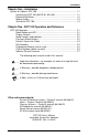
Installation Chapter One - Installation System 5cr Options: SCP 100 ....................................................................... Installing the SCP 100 (60-270-01, 02 & 03) ..................................... Electrical Wall Boxes .......................................................................... Making Cables .................................................................................... Testing the SCP 100 .........................................................................
Installation Notes System 5cr • SCP 100 User’s Manual • Extron
System 5cr SCP 100 Control Panel User’s Manual 1 Chapter One Introduction and Features SCP 100 Installation Installing Electrical Boxes Making Cables Specifications
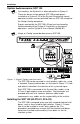
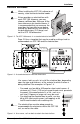
Installation cr Accessories: SCP 100 System 5cr __ For simplicity, the System 5cr is often referred to as System 5. There can be one or two optional SCP 100 remote panels installed on a System 5. All of the System 5 front panel normal operation functions can be controlled from an SCP 100, except for the Setup (Config) procedures. Signals received by the SCP 100’s IR port are transferred by hard-wired cable to the System 5. For details on front panel operations, see the System 5 User’s Manual (68-388-01).
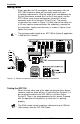
Installation Electrical Wall Boxes ___ When installing the SCP 100, adhere to all country, state and local electrical codes. ___ Extron provides an electrical box with each SCP 100. However, you may choose a different box. Because of the loose tolerances for electrical boxes, it is recommended that you measure the exact box that you plan to use before making any precise cuts. Also refer to the box dimensions (2.5” deep), and not the SCP 100 dimensions.
Installation Making Cables Extron provides the 3.5 mm captive screw connectors with the SCP-100, however a cable will have to be made to fit your installation requirements. Wire the cable to be used between the System 5 connector marked Aux1 or Aux2 (rear panel) and the SCP 100 for a one-to-one configuration (wire pin #1 of one connector to pin #1 of the other, #2 to #2, etc.) The contact assignments are shown in Figure 1-5. Both ends of the cable use a 3.5 mm, captive screw connector.
System 5cr SCP 100 Control Panel User’s Manual 2 Chapter Two Operation SCP 100 Panel Buttons Engineering Drawings Index for System 5cr
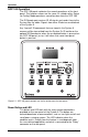
Operation SCP 100 Operation The SCP 100 panel replicates the normal operations of the front panel. The function names are the same. As stated earlier, Setup (or Config) Mode operations cannot be done from the SCP 100. The IR Remote port receives IR 40 signals and sends them to the System 5 by the cable. Signals from other IR devices are blocked at the System 5.
Operation The Room button can operate in one of two ways: latching (press on, press off) or momentary (press on, release off). This programming can only be done through Windows® Control Program (RS-232). _ For example, pressing the Room button once could lower a screen and turn room lights off and the LED will remain lit. Press the button again to turn the room lights on, raise the viewing screen and the LED goes out. Display Controls ___ These buttons only function after being programmed.
Reference Extron’s Comm-Link cable Comm-Link cable was designed for installations such as the System 5. You may choose to use this or a similar low-loss cable. Pin assignments and suggested Wire usage is as follows: A = Signal without carrier (violet or blue) = 22 AWG B = Ground (black) = 18 AWG C = Signal with carrier (white) = 22 AWG D = Ground (Drain) = 24 AWG E = +12V (red) = 18 AWG Figure 2-2. Extron’s Comm-Link cable was designed for use with the SCP 100.
Reference Engineering Drawing (not to scale) This drawing may be used to show dimensions and parts of the SCP-100 panel. Figure 2-3.
Reference Cutout Template (drawn to scale) This drawing may be used as a template for cutting a hole to accommodate a 2-gang electrical box. However, because of the loose tolerances for electrical box dimensions, it is recommended that you measure the exact box that you plan to use before making any critical cuts. Figure 2-4. Scale drawing for cutting hole.