
Manual


RJ-45 to RJ-11 Conversion Kit • HSA 400, 402, 452 Installation
RJ-45 to RJ-11 Conversion Kit • HSA 400, 402, 452 Installation
HSA 400, 402, 452 Installation, cont’d
AAP Cables
H
. S
H
IF
T
C
O
M
P
U
TE
R
IN
P
U
T
SE
LE
C
T
A
U
D
IO
R
G
B
5
8
0
x
i
S
I
A
A
P
HSA 402
Mounting
Surface
125 - 50/60 Hz 5A
125 - 50/60 Hz 5A
Full Thread
Mounting Bolts
Flat Washer
IEC Power Cord
4 RJ-45 Connectors
H
S
A
4
0
2
Clamshell
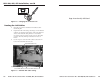
Figure 1-3 — Removing the HSA 402 from the table
2. Through the access hole in the rear of the enclosure,
disconnect the 3-prong cable connector on the interior AC
cable (figure 1-4).
3. Open the top panel and remove and retain the four Allen
screws on the right and left sides of the front panel
(figure 1-5). Lift the front panel away from the enclosure
as far as the connected cables allow.
4. With a tweeker, push down on and gently twist on the
front of each RJ-45 connector detent to disconnect the
connector from the rear of the front panel bezel plug-in.
5. Remove the front panel from the enclosure.
Leave the top panel open for the time being.
Ensure that the edges of the front
panel do not scratch the finished
surface of the top panel flange
when removing the panel.
Figure 1-4 — Disconnecting the interior AC cable
Remove two
Allen screws ea. side.
Lift panel out
of enclosure.
12
5
- 5
0
/6
0
H
z 5
A
HSA 400
H
. SH
IFT
CO
M
PU
TER
INPU
T
SELEC
T
A
U
D
IO
RGB 580
xi
SI AAP
Figure 1-5 — Removing the front panel
Replacing the Lower Enclosure Connector
1. Identify the RJ-45 connector to be replaced.
Simultaneously:
a. With a tweeker in one hand, reach through the small
access hole in the front of the enclosure (figure 1-6)
and gently pry outward on the front of the RJ-45
connector detent on the bezel plug-in,
b. While you reach your other hand through the access
hole in the rear of the enclosure and tilt the connector
back.
This disconnects the connector from the interior of the
lower enclosure without damaging the bezel plug-in.
1-51-4