
Setup Guide Manual
Setup Guide — PVT RGB D and AAP (w/EDID Minder
™
)
Installation
PVT RGB D
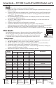
1. Using the supplied mud ring or a junction box (not
included) as a guide, mark and cut out the appropriate
material within the marked area.
N
If installing a junction box, allow enough depth for
the wallplate, connectors, and cables. The depth
should be at least 2.0 inches (5.1 cm).
2. Either:
• Insert the mud ring into the opening, rotate the
locking arms, and secure with the supplied screws, or
• Insert the junction box and secure with nails or screws.
3. Run the CAT 5 cables from the PoleVault switcher
location, going behind the wall and to the PVT
location, then thread the cables through the mud ring
or wall box.
N
The CAT 5 cables supplied with the PoleVault system
are terminated to the TIA 568A standard. Other
CAT 5 cables can be used if they are TIA 568A or
TIA 568B standards and terminated to the same
standard at both ends.
PVT RGB AAP
1. Before attaching any cables, insert the AAP standoffs
through the holes in the faceplate of the device or AAP
wallplate.
2. Using the supplied #4-40 nuts and captive washers,
secure the AAP to the faceplate or wall plate.
3. Be sure to include the AAP connectors as part of the
installation pretest before final faceplate installation.
N
For more detailed installation information, refer to
the installation guide shipped with the device.
The PVT transmitter should be cabled and tested
before it is finally installed into the wall or device
faceplate, as the rear panel connections will be
inaccessible after installation.
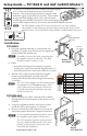
COMPUTER IN
AUDIO IN
IR OUT
S G
Decora
®
Faceplate
Extron
PVT RGB D
Wall
Wall Mounting
Bracket
The Extron
®
PVT RGB D and AAP models with EDID Minder
™
are A/V wall and architectural plates for PoleVault
®
Systems. They transmit high-resolution computer video
and audio signals to the PoleVault switcher. These models
incorporate EDID Minder, which allows the transmitter
to send appropriate EDID information to the source ensuring
correct video output resolution. See reverse side for EDID Minder operation.
N
The EDID Minder settings DIP switch is located on the rear of the wallplate.
Once installed, switch settings are accessible only by removing the device from the
installed location. The factory EDID setting (default) is 1024x768@60 Hz (preset 2).
(Continued on other side)
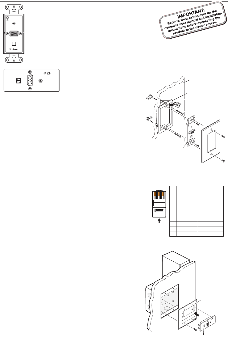
RJ-45 Wiring Table
5
Pin
1
2
3
6
7
8
4
Wire Color
White-green
Green
White-orange
White-blue
Orange
White-brown
Brown
568A
Blue
Wire Color
568B
White-green
Green
White-orange
White-blue
Orange
White-brown
Brown
Blue
12345678
RJ-45
Connector
Insert Twisted
Pair Wires
Pins:
COMPUTER IN
AUDIO IN
IR OUT
S G
AAP 102
Extron
PVT RGB AAP
AAP 102
PVT RGB
COMPUTER
IN
AUDIO IN
PVT RGB AAP
IR
OUT
S
G
COMPUTER
IN
AUDIO IN
PVT RGB AAP
IR
OUT
S
G