User Guide POLEVAULT SWITCHERS PVS 405D PoleVault Digital Switcher 68-2379-01 Rev.
Safety Instructions Safety Instructions • English WARNING: This symbol, , when used on the product, is intended to alert the user of the presence of uninsulated dangerous voltage within the product’s enclosure that may present a risk of electric shock. ATTENTION: This symbol, , when used on the product, is intended to alert the user of important operating and maintenance (servicing) instructions in the literature provided with the equipment.
FCC Class A Notice This equipment has been tested and found to comply with the limits for a Class A digital device, pursuant to part 15 of the FCC rules. The Class A limits provide reasonable protection against harmful interference when the equipment is operated in a commercial environment. This equipment generates, uses, and can radiate radio frequency energy and, if not installed and used in accordance with the instruction manual, may cause harmful interference to radio communications.
Conventions Used in this Guide Notifications The following notifications are used in this guide: DANGER: A danger indicates a situation that will result in death or severe injury. WARNING: A warning indicates a situation that has the potential to result in death or severe injury. CAUTION: A caution indicates a situation that may result in minor injury. ATTENTION: Attention indicates a situation that may damage or destroy the product or associated equipment.
Contents Introduction............................................................ 1 SIS Communication and Control..................... 16 PVS 405D Description......................................... 1 Inputs.............................................................. 1 Outputs........................................................... 2 Control and Configuration................................ 2 Power Save..................................................... 2 Application Diagram.......................
Connector Wiring................................................ 45 Speaker Configuration....................................... 45 Terminating the speaker cable....................... 46 TP Cable Termination and Recommendations... 46 Power Supply Wiring......................................... 47 RS-232 Connector Wiring................................. 48 For IR communication.................................... 49 Input 5 Connector Wiring................................... 51 Warranty.....................
Introduction This manual covers the installation, operation, and configuration of the Extron PVS 405D PoleVault Switcher. Throughout the manual, this switcher is interchangeably referred to as the PVS 405D or the PoleVault switcher or just the switcher. PVS 405D Description The Extron PVS 405D is part of the PoleVault System and is used in conjunction with the Extron PVT series of transmitters and Extron speakers.
Outputs The PVS 405D has one HDMI output, an amplified audio output, and a line out audio output for assistive listening or recording devices. Control and Configuration The PoleVault switcher can be controlled from either the front panel buttons, or software via the front panel USB or RS-232 control via a MediaLink controller. The switcher has an RS-232 port which can be connected to a MediaLink Controller for remote control of the switcher and display.
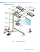
Application Diagram Extron FF 120 Flat Field Speakers - 1 Pair Extron PPS 35 Priority Page Sen ns Sensor TCP/IP P Network rk k (Optional Accessory - mounted m Speaker to Speak S eaker e Front Front Grille) Grille) Extron SPK 18 - 35' Cable Ethernet UTP Cable (CAT 5/5E/6) Extron VLR 102 From PA System To PoleVault Switcher Ce Ceiling Mounted Paging Speaker Pag (rear view) VoiceLift Receiver Extron PCM 340 Projector Drop Ceiling Mount with Adjustable Pole Extron PMK 560 Pole Mount Kit Y ITIVIT SE
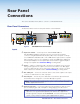
Rear Panel Connections This section describes which cables to connect to a PVS 405D Switcher. Rear Panel Connectors The illustration below shows the rear panel features of the PVS 405D. 7 INPUTS OUTPUT AUDIO OUT L 1/2 POWER 12V 3A MAX SIG 3/4 LINK SIG R +V INPUT 5 12 PVS 405D VOICELIFT AUX 6 2 Figure 2.
Outputs f HDMI video output — Connect a suitable display device to this female HDMI digital video output connector. Use the Extron LockIt device to secure the HDMI cable at the switcher. See “Securing the HDMI cable” on page 7 for method of securing the cable. g Line out audio output — Connect an external amplifier, recording, podcasting, or assisted listening device to this 3.5 mm captive screw 5-pole connector. h Amplified audio output — Connect speakers to this 5 mm captive screw 4-pole connector.
NOTES: • Use only the supplied 12 V, 4 A power supply for this switcher. • The PVS 405D power supply can support a typical system: for example, a PVS 405D, 2 PVT Wallplates, 2 or 4 speakers, an MLC 104 IP Plus with an IRCM DV+, and a VoiceLift Microphone system. • If an SCP 104 is used in the system, the MLC 104 IP Plus MUST have its own power supply.
Final Setup With an MLC 104 IP Plus as a standard MLC controller in the PoleVault system package, the PVS 405D switcher completed setup should look similar to the figure below. Ensure all connections are correctly made and secure. NOTE: See the PoleVault System Installation Guide and MLC 104 Plus Series Setup Guide for full MLC installation, configuration, and operating details.
Operation This section of the manual discusses the operation of a PVS 405D device. Topics covered include: • Front Panel Overview • Configuration • Resetting the Switcher • Front Panel Lockout (Executive Modes) • Power Save Modes • Setting Up and Optimizing the Audio Front Panel Overview PVS 405D INPUTS SELECT R 1 CONFIG 2 3 4 Figure 6.
j VoiceLift level adjustment encoder — This allows the user to adjust the level of the VoiceLift (microphone) input level through 43 positions per rotation in 1 dB steps. The VoiceLift Microphone Receiver input range is from -18 dB to +24 dB, default is -3 dB. k VoiceLift level adjustment LEDs — These three LEDs indicate the active audio level (peak, normal and signal).
Resetting the Switcher The switcher can be reset to the factory defaults via the front panel, USB, or RS-232. The reset button on the front panel is a small recessed switch that allows the user to put the switcher into two different reset modes. The PVS 405D switcher reset modes are: • Mode 1: If the Reset Button is held down while the switcher is being powered up, the switcher reloads its base factory firmware instead of any newer code that was loaded after it shipped.
Power Save Modes The PVS 405D is an ENERGY STAR qualified device, and has five power modes. See table below for mode descriptions. See the “SIS Communication and Control” section, page 24 for relevant commands. Mode Type Activation Device and System power Wake-up trigger Setup Command 0 Normal None Fully powered. LED is green. N/A Default state, SIS command reset 1 Auto Power Save Timed after setup.
Setting Up and Optimizing the Audio The following steps ensure optimal sound is achieved by configuring the switcher. For each step, refer to the sections indicated for more information. Steps for Optimizing the Audio 1. Ensure all the settings are at default. These are the settings the PVS has upon initial power up. The default settings are as shown below. • Volume is set at 80%. • Bass and treble are set at 0. NOTE: Output volume can be adjusted via USB, RS-232, or configuration software. 2.
Gain Control Individual channel input sensitivity control Individual channel input gain control adjustments are made by rotating the adjustment encoder for the selected input button. The adjustment range is -18 dB to +24 dB, with the default set at 0 dB. NOTE: Adjusting input sensitivity for all inputs ensures that all inputs are at the same level and at the highest level possible before clipping occurs.
Bass and treble control For optimum audio quality, the audio input levels and the bass and treble controls must all be set up properly. Input audio levels may need to be adjusted depending on the variation of the output levels from different source devices. NOTE: By default these levels are set for the consumer product level of ‑10 dBV. Bass and treble should be adjusted once the input and output levels have been adjusted.
Paging sensitivity adjustment When the Priority Page Sensor, or the PPS 35 microphone interface, or the Priority Page Sensor kit is connected to the Priority sensor input on the rear panel, the HDMI output audio, amplified and line out audio outputs are muted during a system announcement. The yellow LED indicator lights up as an announcement or page is made over the facility PA system. The Priority Page Sensor kit works with 25V/70V and 4/8 ohms paging systems.
SIS Communication and Control The PVS 405D can be configured and controlled via a host computer or other device (such as a control system) attached to the rear panel RS-232 connector or a LAN port or the front panel USB port (recommended). Control is made using the Extron Simple Instruction Set (SIS) of commands, or the Product Configuration Software (PCS) program. Commands can be entered using a Telnet application such as the Extron DataViewer, available at www.extron.com.
Error Responses When the PVS 405D receives a valid command, it executes the command and sends a response to the host device. If the unit is unable to execute the command because the command contains invalid parameters, it returns an error response to the host.
Symbol Definitions • = Space ] = Carriage return with line feed ¦ or} = Carriage return with no line feed X! = Video and audio input selection, 1-5 X@ = Audio input selection, 1-5, 7 (VoiceLift), 8 (Aux in) X# = PVT wallplate type: 0 = No PVT wallplate detected 1 = PVT SW HDMI D wallplate is detected 2 = PVT SW HDMI RGB D wallplate is detected X$ = Audio input 1 = Active Program (post switch) 7 = VoiceLift 8 = Aux X1) = Audio Status: Signal detection threshold: 0 = Off (signal level is too low to detect) 1
X1* = EDID (DDC) values: (1-61), see table below SIS X1* variables for EDID resolution/refresh rate combination (where X1* = 1 through 61) Resolution Refresh (Hz) Rate Type Video Format Audio Format X1* Resolution Refresh (Hz) Rate Type Video Format Audio Format X1* 800x600 60 PC VGA N/A 1 800x600 60 PC HDMI 2-ch 33 1024x768 60 PC VGA N/A 2* 1024x768 60 PC HDMI 2-ch 34 1280x720 60 PC VGA N/A 3 1280x768 60 PC HDMI 2-ch 35 1280x768 60 PC VGA N/A 4 1280x80
X2* = Power save mode/state: 0 = auto power save and standby power mode off (power save off) (default) 1 = set auto power save timer running, but not triggered 2 = force auto power save on 3 = force standby power save on 4 = force network standby power save on (turn off network switch) X2( = Temperature in °C.
SIS command definitions X10) = Default name: combination of model name and last 3 hex pairs of MAC address (for example PVS-405D-06-DE-2E). X10$ = Hardware (MAC) address: (00-05-A6-xx-xx-xx) X11) = Verbose/Response mode, (default = 0 for telnet connections, 1 for RS-232 and USB host control). 0 = Clear/none; 1 = Verbose mode 2 = Tagged responses for queries 3 = Verbose mode and tagged responses for queries.
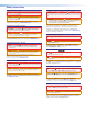
SIS Command and Response Table Command ASCII Command (host to switcher) Response (switcher to host) Additional Description Input selection Select a Video and audio input View current input X!! Chn X!] Select video and audio from input X!. View current selected input X!. ! X!] Verbose response ChnX!] Mute video 1B Vmt1] Mutes video and displays black video on the output. Unmute video (default state) 0B Vmt0] Un mute video output (default).
Command ASCII Command (host to switcher) Response (switcher to host) Additional Description Input audio gain and attenuation NOTE: The VoiceLift and Aux input audio are independent and not affected by the output volume. Set specific input gain/attenuation X@*X3%G InX@•AudX3%] Set gain/attenuation on specified input X@ to X3% dB. Increment specific input gain X@+G InX@•AudX3%] Increment specific input X@ audio level (up).
Command ASCII Command (host to switcher) Response (switcher to host) Additional Description Power save mode Power save off E0PSAV} PsavX2*] Turns off power save mode and sets timer to zero (default). Enable Auto power save on E1PSAV} PsavX2*] Timer start count but is not triggered. Switcher goes into auto power save mode when there is no active AV signal for 25 minutes. Force auto power save on E2PSAV} PsavX2*] Turns on auto power save mode.
Command View Aux input Signal, Normal, and Peak status View video signal presence ASCII Command (host to switcher) Response (switcher to host) 5S SigX1)•NormX1) •ClpX1)] Verbose response Sts05*SigX1)•NormX1)• ClpX1)] ELS} SigX1@•X1@•X1@•X1@] Verbose response SigX1@•X1@•X1@•X1@] Additional Description View Aux input audio Signal, Normal, and Peak status. View which input video signals are present for selected wallplate. NOTE: Command is for selected PVT wallplate only.
Command ASCII Command (host to switcher) Response (switcher to host) Additional Description EDID Minder NOTES: • The switcher and PVT wallplate have two default EDIDs: 720p @ 60 Hz (digital), and 1024x768 @ 60 Hz (analog). • The default EDID of 720p @ 60Hz, 2-CH is always present at inputs 1-4 when no PVT wall plates are detected.
Command ASCII Command (host to switcher) Response (switcher to host) Additional Description Special functions Set lineout mode Set lineout to variable 55*1# LineOut*X] Set lineout port mode to variable (X=1, default). Set lineout to fixed 55*2# LineOut*X] Set lineout port mode to fixed (X=2). View lineout mode 55# LineOut*X] View lineout port mode (X= 1 or 2). Set audio output mode to dual mono 18*1# PreAmpMod*X] Set audio output mode to dual mono (X=1, default).
Command ASCII (Telnet) Response (host to switcher) (switcher to host) Additional Description Decrement horizontal start value EX3^-HSRT} HsrtX3^*X3*] Decrease horizontal start to X3* for X3^. View horizontal start value EX3^HSRT} X3*] View horizontal start X3* for X3^. Verbose response HsrtX3^*X3*] Set vertical start value EX3^*X3(VSRT} VsrtX3^*X3(] Set vertical start at X3( for X3^. Increment vertical start value EX3^+VSRT} VsrtX3^*X3(] Increase vertical start to X3( for X3^.
Command ASCII (Telnet) Response (host to switcher) (switcher to host) Additional Description Query updated firmware version 4Q X12)] Use this command to find out which version of firmware has been uploaded into the processor post-factory. Example: 4Q Ver04*1.00 In this example, firmware version is 1.00. Request switcher part number N 60-1235-01] Show switcher part number. Request AV input number I VidX!•AudX!] Show current active video and audio inputs.
PVS 405D • SIS Communication and Control 30
Using the Extron Product Configuration Software The Extron PVS 405D Product Configuration Software (PCS) offers another way to control the PVS 405D via USB or rear panel RS-232 connection, in addition to using the SIS commands. This section describes installation, communication, and control.
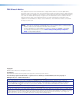
Starting the PVS 405D Product Configuration Software NOTE: The following pages cover PCS version 1.x installations only. If you have installed PCS version 2.x, open the embedded PCS Help file and follow the instructions to access and configure your switcher. 1. Locate and click C:\Program Files(x86)\Extron\Extron PCS\ EAF.exe. This opens the PCS program. Alternatively, if an icon was installed on the desktop, PCS can be started by double-clicking on the icon. The PCS startup window appears. Figure 14.
Figure 15. New Device Page in Emulate/Offline Mode Using the PVS 405D Product Configuration Software — Menus NOTE: For detailed software navigation open the PVS 405D Product Configuration Software Help file. There are two main menus shown at the top of the window. These are Connections and Tools. Connections Menu This menu has five options: Connect, Disconnect, Save Device, Load Different Config File to this Device, and Exit Application.
Save Device All audio, video, input configuration settings, HDCP settings, EDID Minder settings and audio settings from a PVS 405D can be exported to a PC using the Windows Control Program. This exported device file (*.eaf) can be saved as a backup, or be used to “clone” settings from one PVS 405D to others. To Save a Configuration: 1. Select Save Device from the “Connections” drop-down menu. 2. Select a location on the PC to save the configuration, and provide a folder name. 3.
If you are not connected to the device, the Update Firmware submenu is not available. 2. Click OK. A separate window opens and the details of the device and current installed firmware is acquired. 3. Browse to and select the downloaded firmware file. Valid firmware files have an S19 file extension. 4. Click Open. This returns you to the Update Firmware dialog box. 5. Click Update. The progress bar shows the progress of the firmware upload to the device. After uploading is completed, the device restarts.
Using the PVS 405D Product Configuration Software — Pages There are two main pages for configuring the PVS 405D: the Configuration page and the Hardware page. Configuration Pages NOTE: From the Hardware page, click on the Configuration tab The Configuration pages options are: • Input Configuration • EDID Minder . • Audio Configuration Figure 16. Global Navigation Bar for the Configuration Page The browser screen is set out as two sections.
Video and audio mute buttons Select Video Mute to mute only the video signal. The button turns red when mute is applied. Select Audio Mute to mute only the audio. The button turns red. To unmute any signal, click on the appropriate button. The button reverts to the default color, indicating the signal has been unmuted. Input Configuration Page Click on this button to open to this page. Input Configuration panel The Input Configuration panel consists of fields for each of the inputs.
EDID Minder Page Extron EDID Minder is an EDID management process that automatically manages the EDID information between a digital display device and one or more input sources. to open the EDID Minder page. Click on this button From this page an EDID data set can be assigned to any input with an RGB or an HDMI or DVI input type. The currently assigned EDID properties can be viewed and EDID files can be loaded to and from the PVS 405D. Figure 19.
Assigning EDIDs To assign EDID to selected inputs: 1. From the inputs screen (table of inputs) on the right, select the desired input or inputs (see figure below). 2. From the table, select an available EDID (represented by a blue, green, or yellow output display icon). 3. Click the Assign button to assign EDID to the selected input or inputs. Figure 20. Assigning EDIDs NOTE: If you do not select any inputs but still click Assign, an error message is displayed. To assign EDID to all inputs: 1.
Audio Settings Page Using this page each of the audio inputs can be configured, including setting the input format and the gain (for analog inputs only). Mic, Aux, and Paging input settings can also be configured. to open the Audio Config page. Click on this button Figure 21. Audio Config Page Input/ Output To configure audio inputs: 1. Using the input buttons in the AV Controls panel to the left, select the applicable input. 2.
Mic/Aux/Paging Using this page to set the input gain, and where desired, ducking can be enabled and settings configured for both VoiceLift and Aux inputs. In addition the Page Sensor sensitivity and hold time can be set from this page. Figure 22.
Hardware Pages Click on the Hardware tab to open these pages. The Hardware pages options are: • Unit Information • Device Name • Executive/Power Mode • Reset Device Figure 23. Global Navigation Bar for the Hardware Page Unit Information Page This page gives a non-configurable view of information about the connected unit. These include part number, model name and description, firmware version and build number. Click on this button to open the page. Figure 24.
3. Enter a name for the device. The name may be up to 24 alphanumeric characters in length. 4. Click Apply. To reset the name of the device, click Reset to Default. The default name is the model name followed by the last six digits of the device MAC address (see image above). Executive/Power Mode Page This page allows the user to set the executive mode and power mode for the device. Click on this button to open the page. Figure 26.
Reset Device Page This page allows the user to reset the device to factory defaults. Click on this button to open the page. Figure 27. Reset Device Page To reset the device: 1. Click Reset. A confirmation dialog box opens. 2. In the dialog box, click Reset to continue with the reset, or Cancel to abort the reset. 3. A confirmation dialog box appears confirming the device has been reset.
Connector Wiring This section of the manual discusses the connector wiring for a PVS 405D device. Topics covered include: • Speaker Configuration • TP Cable Termination • Power Supply Connector Wiring • RS-232 Connector Wiring • Input 5 Connector Wiring Speaker Configuration When setting up a speaker configuration, the correct speaker impedance loading must be observed.
Terminating the speaker cable To terminate the cable, strip the end of the cable 0.2 inch (5 mm) and secure the wires into the supplied 4-pole captive screw connector. Speaker wire color Speaker 1 Speaker 2 To PVS 405D terminal (Left and Right) Red Positive (+) Black Negative (-) Audio output to speakers 4-pole Captive Screw Connector AMPLIFIED OUTPUTS 4/8 Ohms L R PVS Switcher Rear Panel Figure 30.
Power Supply Wiring NOTE: Use only the supplied 12 V, 4 A power supply for this switcher. The PVS 405D power supply can support a typical system: for example, a PVS 405D, 2 PVT Wallplates, 2 or 4 speakers, an MLC 104 IP Plus with an IRCM DV+, and a VoiceLift Microphone system. If an additional SCP 104 is used, the MLC 104 IP Plus MUST have its own power supply. Figure 31 shows how to wire the connector. 3/16" (5 mm) Max.
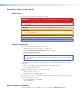
RS-232 Connector Wiring Figure 33 shows the wiring for the PVS 405D and the MLC 104 IP Plus RS-232 connectors . REMOTE RS-232 PVS 405D Remote RS-232 Port Tx Rx G NOTE: You must connect a ground wire between the MLC and PVS 405D. G Ground Transmit (Tx) B Receive (Rx) A MLS +12V IN Tx A B GROUND Rx NOTE: If you use cable that has a drain wire, tie the drain wire to ground at both ends.
For IR communication Connect the IR/RS-232 projector communication cable for either RS-232 or IR projector control. RS-232 connection RS-232 to projector IR OUT Rx Tx GROUND Transmit (Tx) Receive (Rx) Ground DISPLAY RS-232/IR MLC 104 IP Plus Right Side Panel Terminal RS-232 Cable color Pin Tx White 2 Rx Violet 3 Ground Shield 5 Figure 35. RS-232 Connection to Projector IR connection Black IR Emitter Ground IR Signal Unidirectional IR Output via White Striped Wire 100' (30.
NOTE: Some projectors require NULL connection wiring, which inverts the Tx and Rx connections. See the projector guide for details. IR control for a connected input device such as a BluRay player can be made through the PVT wallplate. The connections between the MLC 104 IP Plus and the PVS 405D switcher should look like the figure below.
Input 5 Connector Wiring Input 5 is a dedicated-audio only input for an auxiliary, stereo, line-level analog audio signal from an output source such as an iPod device or an MP3 player. Connect the cable from the source to this 5‑pole captive screw connector. The connector can be wired as balanced or unbalanced as shown below. NOTE: Input 5 is audio only. No video signals are supported on this input.
Extron Warranty Extron Electronics warrants this product against defects in materials and workmanship for a period of three years from the date of purchase.