
Setup Guide User Manual

PVS 405D • Setup Guide (Continued)
2
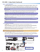
Step 1 — Connect A/V inputs
a HDMI and RGB video and audio inputs — Using recommended TP cables (see the Notes re cables on page 1), connect
up to four HDMI or RGB input sources via the PVT SW HDMI RGB D or PVT SW HDMI D input wallplates to these two RJ-45
female connectors. These inputs can be four HDMI with embedded audio, or two HDMI and two high resolution computer
video and audio sources, or a combination. The front panel input selection button toggles the inputs 1 through 4 as required.
NOTE: Each PVT input wallplate supports two input sources. A maximum of two PVT input wallplates can be connected
to the PVS 405D.
b
Audio input — Input 5 is a dedicated-audio only input for an auxiliary, stereo, line-level analog audio signal from an
output source such as an iPod device or an MP3 player. Connect the cable from the source to this 5-pole captive screw
connector. The connector can be wired as balanced or unbalanced (see the PVS 405D User Guide for method).
NOTE: Input 5 is audio only. No video signals are supported on this input.
c
Aux input — Connect an auxiliary audio device to this 3-pole captive screw connector. It can be wired for balanced or
unbalanced mono audio. Aux audio can be congured to duck program audio or to be mixed with program audio (inputs 1-5).
d
VoiceLift receiver connection — Connect an optional Extron VoiceLift receiver to this RJ-45 connector for the
integration of a VoiceLift Microphone system.
NOTE: The Extron VoiceLift Microphone Kit is an optional accessory and must be purchased separately.
e
Paging sensor input — Connect the optional Extron Priority Page Sensor Kit to this port, to enable program audio
interruptions during paging system broadcasts.
NOTE: Priority Page Sensor Kits (part numbers 70-1064-01 or 70-619-01) are optional accessories, purchased separately.
3A MAX
POWER
12V
HDMI
1/2
SIG LINK SIG LINK
3/4
INPUTS OUTPUT AUDIO OUT
PVS 405D
PAGING
SENSOR
PVT IN PVT IN
L
R
AUX OVER PVT REMOTE
VOICELIFT
LAN 1 LAN 2 LAN 3
INPUT 5
+V
L
R
RS-232
Tx Rx
IR
SG G
2
3
GROUND
1
IR IN
GROUND
IR OUT
CM
SCP
GROUND
GROUND
Tx
Rx
DISPLAY
RS-232/IR
LAN
PRESS TAB WITH
TWEEKER TO REMOVE
A B
MLS PWR
RS-232 12V
DIGITAL
I/O
A B C D E
COMM LINK
+V OUT
GROUND
Tx
Rx
+12V IN
CONFIG
DISPLAY
VOLUME
MLC 104 IP PLUS
ON
VCR
DVD
PC
OFF
1
2
3
4
RS-232
MLC 104 IP Plus right side panel
MLS and Power ports
RS-232 12V
MLS PWR
AB
Rx
Tx
GROUND
GROUND
+12V IN
NOTES:
• You must connect a ground wire
between the MLC and PVS.
• If you use cable that has a drain
wire, tie the drain wire to ground at both ends.
G
Ground
+12 VDC input
Ground (Gnd)
Transmit (Tx)
B
Receive (Rx)
A
Transmit (Tx)
Receive (Rx)
Tx
Rx
IR control
S
Ground
G
IR Out
Rx
Tx
Projector
GROUND
IR OUT
Tx
Rx
DISPLAY
RS-232/IR
Ground
RS-232
To Supplied PVS Switcher Power Supply
(12 VDC, 4 A max.)
LR
DO NOT
GROUND
OR SHORT
SPEAKER
OUTPUTS
4/8
Ω
AMPLIFIED AUDIO OUT
CLASS 2 WIRING
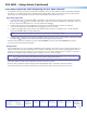
Step 2 — Connect A/V Outputs
f
HDMI output — Connect an HDMI capable display or the projector to this female HDMI connector.
g
Audio Out (line level) — This port is used for connecting an external Extron audio amplier, a recording podcasting
device, or an assistive listening system. It can be congured via RS-232 or USB for xed or variable audio output (default is
variable). It can be wired for balanced or unbalanced signals (see the PVS 405D User Guide for method)..
h
Amplified Audio Out — Connect speakers to each channel marked “L” and “R” (left and right) using the supplied black
4-pin, 5 mm connector. Wire red to positive, black to negative. Each channel is rated for 25 W at 4 or 8 ohm loads.
If using more than one speaker per channel, connect them in parallel.
ATTENTION: DO NOT tie L and R outputs to each other and/or to ground as it will short the outputs and damage the amplifier.
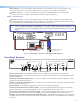
Step 3 — Connect Remote Control, IR, and LAN Connectors
i
Remote (RS-232/MLC) control port — The PVS switcher can be controlled via an RS -232 connection directly from a
host computer, a control system, or a MediaLink
®
Controller (MLC). The MLC provides remote control of input switching and
volume. Connect a cable between this port and the MLC MediaLink Controller (see gure 2). The RS-232 protocol is 9600
baud, 8-bit, 1-stop bit, no parity, and no ow control. See the MLC 104 IP Plus User Manual for full details.
NOTE: To power the MLC 104 IP Plus wire it directly into the same power supply the switcher uses (see gures 2 and 3).
Figure 2. MLC 104 IP Plus to PVS 405D Connection