
Installation guide


VoiceLift System with PVS 405D Installation Guide • Introduction 3
Planning the Installation
Before you begin the installation, consider the major factors discussed in the following
sections to ensure that the installation of the VoiceLift System is as smooth and trouble
free as possible and that the result meets the needs of the users. Placement of the
receiver (sensor location) is very important for optimal performance of the VoiceLift
System. Because IR technology requires line-of-sight placement, take into consideration
anything that could affect or block the transmission of the IR signal from the microphone
to the receiver (see Room Considerations on the next page).
LR
DO NOT
GROUND
OR SHORT
SPEAKER
OUTPUTS
4/8
Ω
3A MAX
POWER
12V
HDMI
1/2
SIG LINK SIG LINK
3/4
INPUTS OUTPUT AUDIO OUT
PVS 405D
AMPLIFIED AUDIO OUT
PAGING
SENSOR
PVT IN PVT IN
L
R
AUX OVER PVT REMOTE
VOICELIFT
LAN 1 LAN 2 LAN 3
INPUT 5
+V
L
R
RS-232
Tx Rx
IR
SG G
Out
In
VLR 102
Receiver
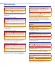
5 ft. (1.5 m) to 40 ft. (10.2 m)
Figure 2. VoiceLift Connections and Signal Path
Receiver Coverage
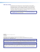
The VoiceLift receiver has the same room coverage pattern whether it is mounted on the
ceiling or a wall.
VoiceLift
Receiver
VoiceLift
Microphone
Ceiling or Wall
Figure 3. VoiceLift Receiver Coverage
NOTE: Coverage is dependent mainly on the room environment, but also on the
microphone. You can attain maximum coverage when the batteries are fully
charged. Reception may decrease as the battery drains.