
Installation guide


Stage 4:
Connecting the
Cables
This stage consists of connecting the receiver and speakers to the PoleVault switcher.
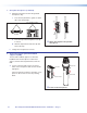
Receiver Dome
Locking
Tab (4)
RJ-45 Connectors
Captive Screw Connectors
DIP Switches
Locking Tab
with Arrow
Figure 16. Receiver Dome Features
Where it goes: Attaches to the receiver housing.
What it does: Receives signals from the microphone and sends them to the
switcher or amplier. Its top panel contains photodiode IR
sensors (inside), captive screw connectors for auxiliary input,
RS-232, contact input, and relay output; RJ-45 connectors for
power, communication, and audio output; and DIP switches.
STP Cable
Figure 17. STP Cable
Use a CAT 5, 5E, 6, 7 screened shielded twisted pair cable with T568A or T568B
straight-through wiring.
Where it goes: Attaches to the receiver RJ-45 Out port and to the VoiceLift
Receiver RJ-45 port on the PVS 405D switcher.
What it does: Provides power to the receiver and enables communication and
audio between the receiver and the PoleVault switcher.
VoiceLift System with PVS 405D Installation Guide • Installation — Stage 4
28