
User Guide Owner's manual


Quick Start — PVS 204SA
Installation
This Quick Start section deals specifically with
quick connectivity and installation of the
PVS 204SA PoleVault
™
switcher. At this stage,
it is assumed that all of the necessary cable
routing has been completed, and that projector
ceiling hardware (e.g. ceiling mounts, projector
poles, projector mounting kits) and output
devices have been installed. Also, any PVT
transmitters should already be installed (but not
yet connected) following the relevant supplied
instruction manuals.
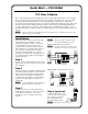
Step 1
Remove power from the switcher and any input,
output, and control devices that are to be used in
this installation.
Step 2
Using the supplied colored labels, label both ends
of all audio/video input cables. Ensure that the
labels used match the input signal type that the
cable will carry. See chapter 2, “Installation”,
“Labeling and connecting the A/V input cables”
section, for wiring diagrams and input color
coding table.
N In some installations it may be prudent to
label the cables before routing them.
Step 3
Connect input devices via PVT transmitters to
the RJ-45 inputs on the rear of the PVS switcher.
See chapter 2, “Installation”, “A/V input
connections” section, for details and wiring
diagrams.
N Labeling the cables correctly using the
color code will make this step easier.
Inputs 1 and 2: RGB video and audio.
N Two cables (A and B) are needed for each
RGB input. Do not cross connect them.
PVT RGB D
Input #2
PVT RGB D
Input #1
POWER
12V
3A MAX
I
N
P
U
T
S
RGB
RGB Input Connectors on
Rear Panel of PVS 204SA
Cable from
PVT Output A
Cable from
PVT Output B
B
A
A
B
Rear Panel
Rear Panel
1A
2A
1B
2B
Cable from
PVT Output A
Cable from
PVT Output B
Inputs 3 and 4: Composite video and audio.
VIDEO
PVT CV D
Input #3
Cable from
PVT Output
PVT CV D
Input #4
Rear Panel
Rear Panel
Composite Video Input
Connectors on
Rear Panel of PVS 204SA
Cable from
PVT Output
3
4
Step 4 (optional)
Connect a mono audio source
to the Aux/Mix audio input on
the rear panel to mix a line-
level audio signal with
the selected input’s audio.
N This channel is always active.
AUX/MIX IN
+ Positive
– Negative
Ground
FCC Class A Notice
Note: This equipment has been tested and found to comply with the limits for a Class A digital
device, pursuant to part 15 of the FCC Rules. These limits are designed to provide reasonable
protection against harmful interference when the equipment is operated in a commercial
environment. This equipment generates, uses and can radiate radio frequency energy and, if not
installed and used in accordance with the instruction manual, may cause harmful interference
to radio communications. Operation of this equipment in a residential area is likely to cause
harmful interference, in which case the user will be required to correct the interference at his own
expense.
N This unit was tested with shielded cables on the peripheral devices. Shielded cables must be used
with the unit to ensure compliance.