PVS 204SA PoleVault™ Switcher 68-1217-01 Rev.
Precautions Safety Instructions • English Warning This symbol is intended to alert the user of important operating and maintenance (servicing) instructions in the literature provided with the equipment. Power sources • This equipment should be operated only from the power source indicated on the product. This equipment is intended to be used with a main power system with a grounded (neutral) conductor. The third (grounding) pin is a safety feature, do not attempt to bypass or disable it.
Quick Start — PVS 204SA FCC Class A Notice Note: This equipment has been tested and found to comply with the limits for a Class A digital device, pursuant to part 15 of the FCC Rules. These limits are designed to provide reasonable protection against harmful interference when the equipment is operated in a commercial environment.
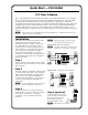
Quick Start — PVS 204SA, cont’d Step 5 Connect cables from the switcher’s RGB and composite video output connectors to the inputs on the display device (e.g., projector). Input Cables from Transmitters (AV control) FRONT Step 11 Set up and optimize the audio (gain control and input sensitivity) for each input, including Aux/ Mix. This can be done via the front panel or by RS-232 control. See chapter 3, “Operation and Setup”, “Setting Up and Optimizing the Audio” section, for details.
Table of Contents Chapter 1 • Introduction ............................................................................................................. 1-1 About this Manual .................................................................................................................... 1-2 About the PVS 240SA .............................................................................................................. 1-2 TP cable advantages............................................................
Table of Contents, cont’d Clipping indicator ..................................................................................................................... 3-7 Bass, treble, and loudness control........................................................................................... 3-7 Aux/Mix control . ....................................................................................................................... 3-7 Resetting the Switcher . ...............................................
PVS 240SA 1 Chapter One Introduction About this Manual About the PVS 240SA Application Diagrams
Introduction About this Manual This manual covers the installation, operation, and configuration of the Extron PVS 204SA PoleVault™ Switcher. Throughout the manual, this switcher is interchangeably referred to as the PVS 204SA, PVS switcher, PoleVault switcher, PVS, and switcher. About the PVS 204SA The Extron PVS 204SA is a four input, two output, twisted pair, audio and video switcher with a built in audio amplifier.
Features Twisted pair inputs — The switcher accepts two independent, high resolution RGB video and audio signals and two composite video and audio signals, transmitted on twisted pair cable from a source up to 100' (30 m) away. Video output — The PVS switcher can switch between four inputs (two RGB and two composite). Aux/Mix input — The PVS switcher can mix a mono line level audio input with the audio input from the video/audio source.
Introduction, cont’d Application Diagrams PCM 240 4 4 Projector Drop Ceiling Mount Audio Ceiling Mounted AC Outlet Audio PV SI 3C LP Full Range Single Driver Ceiling Speakers 7 AC for PoleVault System Video In 8 AC for Projector IN DIO AU ER IN UT MP CO 1 (x2) PMK 450 Multi-product Pole Mount Kit PVT RGB D 1 Gang RGB and Audio Input Video In DIO AU PVS 204SA IN PoleVault Switcher L R EO 1 IN VID D AMP S s PUTOhm OUT4/8 LIFIE Line Level Audio R ND GROU T TS! NOTSHOR DO OR
PCM 240 4 4 Projector Drop Ceiling Mount Audio Ceiling Mounted AC Outlet Audio PV SI 3C LP Full Range Single Driver Ceiling Speakers 7 AC for PoleVault System Video In 8 AC for Projector CO MPU IN TER AU DI O IN 1 TP ST RG B (x2) PMK 450 Multi-product Pole Mount Kit PVT RGB D 1 Gang RGB and Audio Input Video In PVS 204SA PoleVault Switcher VIDE IN O R AU AC 1 DI O L IN TP ST T IV E AP 1A CV D AMP MU S s PUTOhm OUT4/8 SPEAK L /IR MLC12V 32 IR RS-2 Rx Tx DC VOL
Introduction, cont’d 1-6 PVS 204SA Switcher • Introduction
PVS 240SA 2 Chapter Two Installation UL/Safety Guidelines Mounting the Switcher Rear Panel Features and Cabling Speaker Configuration Labeling the A/V Inputs Final Setup
Installation UL/Safety Guidelines The Underwriters Laboratories (UL) guidelines listed below pertain to the safe installation and operation of this switcher. PRELIMINARY Important safety instructions 1. Read these instructions. 2. Keep these instructions. 3. Heed all warnings. 4. Follow all instructions. 5. Do not use this apparatus near water. 6. Clean only with a dry cloth. 7. Do not block any ventilation openings. Install in accordance with the manufacturer’s instructions. 8.
Mounting the Switcher The PVS 204SA can be mounted on the Extron PMK 450 (Pole Mount Kit), which should be installed above the projector. The low profile of the PVS switcher and the PMK 450 allows them to be installed in tight spaces. To install the PVS 204SA on the PMK, follow the steps shown in the instruction guide supplied with the PMK 450. If the PMK 450 is already installed, do the following: 1.
Installation Rear Panel Features and Cabling 3 4 VIDEO 33 RGB 2 RGB 1A 1A 2A 2A 10 POWER I N P U T S O U T P U T S 1B 1B 12V 3A MAX 2B 2B 44 1 AMPLIFIED OUTPUTS LISTED 17TT US AUDIO/VIDEO ® STEREO ON HIGH PASS FILTER 5 AUX/MIX IN ON 6 L RS-232 MLC/IR Tx Rx IR 12V A B C DUAL MONO OFF VIDEO 4/8 Ohms APPARATUS 7 R DC VOL 10V VOL/MUTE 9 8 Figure 2-2 — Features of the PVS 204SA Switcher rear panel Power connection PRELIMINARY a DC power connector — Attach the supplied male
N RJ-45 termination must comply with the TIA/EIA T 568A or 568B wiring standards for all connectors. The same standard MUST be used at both ends of all cables. N The RGB cables supplied with the PoleVault system are terminated to the TIA 568A standard, as shown in figure 2-4. Pins: 12345678 568A Pin Wire Color Cable A Cable B 1 White-green Red + V. sync + 2 Green Red – V. sync – 3 White-orange H. sync + + 5 VDC 4 Blue Green + Audio L + 5 White-blue Green – Audio L – 6 Orange H.
Installation, cont’d N RJ-45 termination must comply with the TIA/EIA T 568A or 568B wiring standards for all connectors. The same standard MUST be used at both ends of all cables. N The composite video cables supplied with the PoleVault system are terminated to the TIA 568A standard, as shown in figure 2-6.
ã Stereo and Dual Mono selection — To select stereo or dual mono audio output, set the switch to the desired position. Dual mono sums left and right audio signals together and outputs the same signals on both audio output channels. Default setting is mono. N For best results when speech is the primary audio, set this switch for dual mono with the high pass filter set to on. If music is involved, set the switch to stereo with the high pass filter set to off.
Installation, cont’d Control connection h RS-232/MLC/IR control port — The PVS switcher can be controlled via an RS‑232 connection directly from a host computer, a control system, or a MediaLink Controller (MLC). For IR remote control, connect an Extron IR Link to this port. RS-232 connection can be used to configure the PVS switcher. Connect a cable between this port and an optional Extron MLC MediaLink Controller or an optional IR Link IR signal repeater.
PVS 204SA Switcher’s rear panel RS-232/MLC/IR port 2A RGB POWER 12V 3A MAX A BC D E O U T P U T S 1B 2B DO NOT GROUND OR SHORT SPEAKER OUTPUTS! APPARATUS ON STEREO L RS-232 MLC/IR Tx Rx IR 12V HIGH PASS FILTER OFF 4 AMPLIFIED OUTPUTS 4/8 Ohms LISTED 17TT US AUDIO/VIDEO ® +12V VIDEO DUAL MONO A B C AUX/MIX IN R DC VOL 10V VOL/MUTE PVS 204SA Switcher Rear Panel NOTE If you use cable that has a drain wire, tie the drain wire to ground at both ends.
Installation, cont’d RGB RS-232/MLC/IR Tx Rx IR +12V A B C D E 1A 2A VIDEO 3 RGB POWER IR Link port 12V 3A MAX IR I N P U T S O U T P U T S 1B 2B 4 AMPLIFIED OUTPUTS 4/8 Ohms LISTED 17TT ® A BCD E PVS 204SA Switcher’s rear panel RS-232/MLC/IR port US AUDIO/VIDEO DO NOT GROUND OR SHORT SPEAKER OUTPUTS! APPARATUS ON L RS-232 MLC/IR Tx Rx IR 12V STEREO HIGH PASS FILTER OFF VIDEO DUAL MONO AUX/MIX IN A B C R DC VOL 10V VOL/MUTE PVS 204SA Switcher Rear Panel DVD +12 VDC Ground
j Amplified Out — Wire and connect the supplied 4-pin 5 mm connector to this port, marked “L” and “R” (left and right) for 4 or 8 ohm speaker output. C AMPLIFIED OUTPUTS 4/8 Ohms L R Do not tie both L and R outputs to each other and/or to ground. Doing so will short out the outputs and damage the amplifier.
Installation, cont’d Connecting speakers to the PVS 204SA To obtain the correct impedance loading for your specific speaker system, follow the relevant setup as shown below.
Labeling the A/V Inputs Labeling and connecting the A/V input cables The RGB and composite video input ports on the rear of the PVS 204SA are color coded to aid easy identification of the input signal type. A sheet of corresponding colored labels is supplied for the installer to label the cables running from the PVT transmitters to the switcher.
Installation, cont’d Labeling the PVT Decora face plates To help identify the input number and type of signal that RGB IN #1 any PVT Decora transmitter sends to the PVS switcher when the transmitter is installed, a series of small labels are supplied. A label identifying the transmitted signal type should be affixed to each Decora faceplate (top or bottom) where it can easily be seen after installation.
PVS 240SA 3 Chapter Three Operation and Setup Front Panel Features and Operation Setting Switcher Modes Auto Switching Setting Up and Optimizing the Audio Resetting the Switcher Front Panel Security Lockout (Executive Mode)
Operation and Setup Front Panel Features and Operation PVS 204SA AUTO SW LOCKOUT POLEVAULT SWITCHER 1 2 3 INPUTS 1 RGB AUDIO 3 VIDEO 2 4 CONFIG AUX/MIX MIN/MAX 5 4 6 7 LEVEL CLIP 8 9 Figure 3-1 — Front panel features a b PRELIMINARY c d Power indicator LED — When lit, this green LED indicates that the switcher has power supplied to it. Auto switching indicator LED — When lit, this green LED indicates that the auto switching is turned on.
Min/Max LED — This red LED indicates when the range limits for the power amplifier level, Aux/Mix volume, or input gain level have been reached. See “Setting Up and Optimizing the Audio”, later in this chapter, for details. It lights as follows: • When setting up input levels • When the PVS reaches the min./max. amplifier level • When the PVS reaches the min./max. Aux/Mix level g Aux/Mix level encoder — This recessed rotary encoder allows front panel adjustments specific to the Aux/Mix input level.
Operation and Setup, cont’d Setting the separate switcher mode via the front panel 1. Press and hold input selection buttons 1 and 3 simultaneously for 4 seconds (see figure 3-4). All the input selection LEDs blink once. 2. Release the buttons. The switcher has enabled separate switcher mode and two LEDs remain lit (one for RGB format, one for composite video format). INPUTS 1 RGB INPUTS INPUTS 3 VIDEO 2 4 1 Press and hold buttons 1 and 3 simultaneously for 4 seconds.
Setting Up and Optimizing the Audio The following steps ensure optimal sound is achieved by configuring the PVS 204SA properly. For each step, refer to the sections indicated for more information. Steps for optimizing the audio 1. Ensure all the settings are at default. These are the settings the PVS has upon initial power up. The default settings are as shown below. • Volume is set at 50%. • Bass and treble are set at 0. • Power Amplifier level is set to 50% (default level is 0 dB).
Operation and Setup, cont’d Gain control Individual channel input sensitivity control Individual channel input gain control adjustments are made by rotating the encoder while pressing in the selected input button. The adjustment range is -18 dB to +24 dB, with the default set at 0 dB. N Adjusting input sensitivity for all inputs ensures that all inputs are at the same level, and at the highest level possible before clipping occurs.
Clipping indicator The clipping LED is a real time indicator of when the amplifier is clipping. It flashes red when clipping is taking place (see figure 3-7). AUDIO AUX/MIX MIN/MAX LEVEL CLIP This LED flashes when the amplifier output is clipping. Figure 3-7 — Front Panel audio clipping indicator LED and recessed encoders N To reduce the risk of damage to the speaker, reduce the amplifier level by turning the encoder counterclockwise until the Clip LED turns off.
Operation and Setup, cont’d Front Panel Security Lockout (Executive Mode) To prevent accidental or unauthorized changes to settings, the PVS switcher has a front panel security lockout (executive mode) that limits users’ access to front panel controls. When the executive mode is active, all functions are locked, and a red lockout LED (next to the power LED) lights to indicate that executive mode is on.
PVS 204SA 4 Chapter Four Serial Communication RS-232 Programmer’s Guide Updating Firmware
Serial Communication The PVS 204SA switcher can be remotely set up and controlled via a host computer or other device (such as a control system) attached to the rear panel RS-232/MLC/IR port. Alternatively, the switcher can be controlled by an optional MediaLink Controller (MLC) (connected to the same port) or by an RS-232 device acting through the MLC. The control device (host) can use either Extron’s Simple Instruction Set (SIS™) commands or the Global Configurator RS-232/MLC/IR (GC2) program for Windows.
Error responses When the PVS switcher receives a valid SIS command, it executes the command and sends a response to the host device. If the PVS is unable to execute the command because the command is invalid or it contains invalid parameters, it returns an error response to the host.
Serial Communication, cont’d X$ = 0 – 14, bass and treble adjustment range (+/- 10.5 dB: 1.5 dB increments/decrements), default = 7 = 0 dB Value (dB) 0 -10.5 1 -9 2 -7.5 3 -6 4 -4.5 5 -3 6 -1.5 7 0 8 +1.5 9 +3 10 +4.5 11 +6 12 +7.5 13 +9 14 +10.5 PRELIMINARY X% = X^ = X& = X* = X( = X1) = X1! = -10.5 to +10.
Command/response table for SIS commands Command ASCII Command Response (host to switcher) (switcher to host) Additional description Input selection Select an input (video and audio) Example: Select an input (video and audio) Example: X! ! 2! X! * X1% ! 1*2! Chn X! ] (single sw. mode) Chn2 ] (single sw. mode) Chn X1% * X! ! ] (sep. sw. mode) Chn1*2 ] (sep. sw. mode) Select an audio input Select a video input (single sw. mode) Select a video input (sep sw.
Serial Communication, cont’d Command/response table for SIS commands (continued) Command ASCII Command Response (host to switcher) Additional description (switcher to host) Volume adjustment Set the overall output volume X^ V Vol X^ ] Example: Increment the volume Decrement the volume View the volume level 27V +V -V V Vol027 ] Vol X^ ] Vol X^ ] Vol X^ ] Specify the volume (0-100) for the audio output. Set volume to 27. Increase audio output. Decrease audio output. Show the output volume.
Command/response table for special function SIS commands The syntax for setting a special function is __ * X? #, where __ is the function number and X? is the value. To view a function’s setting, use __#, where __ is the function number. In the following table the values of the X? variable are different for each command/function. These values are given in the right-most column.
Serial Communication, cont’d Updating Firmware If the need arises, you can update the PVS’s firmware without taking the unit out of service. Follow the directions below. Check the Extron Web (www.extron.com) site for firmware-related documents, instructions, patch files, and new firmware files before loading new firmware into the switcher. Extron recommends that you read the firmware release notes (available from the Web site www.extron.com) before beginning the firmware update.
When the browser window opens, click Browse to locate and select the firmware file. 7. Select the firmware file and click Open to open the file. 8. Click Upload to upload the firmware file into the PVS 204SA. PRELIMINARY 6.
Serial Communication, cont’d Wait until the status bar indicates completion. The note “Transfer Complete!” is shown and the unit resets itself. 10. Click Exit to exit the program upon completion. PRELIMINARY 9.
A Appendix A Reference Material Specifications Part Numbers and Accessories Audio Block Diagram Audio Reference Levels
Reference Material Specifications N Where indicated by “†”, the relevant specification is given with the PVS operating as part of a system with proprietary Extron PVT transmitters for this product. Video — RGB Gain ������������������������������������������������ Crosstalk ���������������������������������������� Switching speed ���������������������������� CMRR ��������������������������������������������� Unity † -70 dB @ 5 MHz 1 ms (max.
Video output — composite video Number/signal type ��������������������� 1 composite video Connectors ������������������������������������ 1 RCA female Nominal level �������������������������������� Minimum/maximum levels �������� Impedance ������������������������������������� Return loss ������������������������������������� DC offset ���������������������������������������� 1 Vp-p for composite video (including sync) † 0.4 V to 2.0 Vp-p (follows input) 75 ohms -40 dB @ 5 MHz ±20.
Reference Material, cont’d Audio output — power amplifier Number/signal type �������������������� Connectors ������������������������������������ Impedance ������������������������������������� Amplifier type ������������������������������� Gain/volume adjustment ����������� Frequency response ��������������������� THD + Noise ��������������������������������� S/N �������������������������������������������������� (1) stereo (default) or dual mono, 2 channels total (1) 5.
Part Numbers and Accessories These items are included in each order for an PVS 204SA switcher: Included parts Included parts Replacement part number PVS 204SA switcher 60-800-01 Rubber feet (4) 12 VDC, 3 A external power supply, (1) 5-pole, 3.5 mm captive screw connector, (1) 10-703-12LF 3-pole, 3.5 mm captive screw connector, (1) 10-703-11LF 2-pole, 3.
Reference Material, cont’d Speaker accessories Accessory Part number SI 3C LP, Full-Range Ceiling Speakers, 4" Low Profile Back Can and Transformer 42-103-13 SI 26CT, Two-Way Ceiling Speakers, 8" Back Can and Transformer 42-070-03 SI 26, Two-Way Surface Mount Speakers, 6.5" Woofer 42-072-0x SI 26W, Two-Way In-Wall Speakers, 6.
- + Aux /Mix Input Right Channel - + 7 - + Balanced Line Level Input - 4 + - 3 + - 2 + 1 - 4 + - 2 + Left Channel + 3 1 Twisted Pair Differential Audio Input Input Channel Gain Aux/Mix Level Encoder Audio MUX Audio MUX + PVS 204SA Switcher • Reference Material Tone Controls: Volume, Treble, Bass, Loudness Stereo/Dual Mono DIP Switch Stereo Dual Mono Dual Mono Stereo + + PRELIMINARY High Pass Filter On/Off DIP Switch Mono Sum Power Amp Level Software Controlled OFF O
Reference Material, cont’d Audio Reference Levels PRELIMINARY The specifications for the audio source devices may be listed in one of several units. You may wish to use a sine wave generator such as the Extron VTG 300 as a source for setting up audio inputs before the input devices are available. The tables below are a convenient reference for equivalences between dBV, voltage, and dBu.
Extron’s Warranty Extron Electronics warrants this product against defects in materials and workmanship for a period of three years from the date of purchase.
Extron USA - West Headquarters +800.633.9876 Inside USA / Canada Only +1.714.491.1500 +1.714.491.1517 FAX Extron USA - East Extron EMEA Extron Asia Extron Japan Extron China Extron Middle East +800.633.9876 +800.3987.6673 +800.7339.8766 +81.3.3511.7655 +81.3.3511.7656 FAX +400.883.1568 +971.4.2991800 +971.4.2991880 FAX +1.919.863.1794 +1.919.863.1797 FAX +31.33.453.4040 +31.33.453.4050 FAX +65.6383.4400 +65.6383.