
Manual


5. Close and latch the top of the Priority Page
Sensor. Reconnect the speaker cable to the
speaker.
6. Strip 3/16 inches of insulation from each
conductor on the bare wire end of the remaining
blue sensor cable. Do not tin the leads. Feed the
wire into the junction box (clamping it down if
necessary) and connect the wires to the 2-pole
captive screw connector on the PVS 305SA IP.
Polarity need not be observed
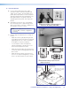
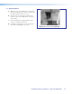
7. If a junction box is being used in a plenum space,
ensure the sensor and all wires fit inside the box
(as shown at right). All cables leaving the box must
be plenum rated. Tighten the cable clamp and
secure the lid to the junction box.
NOTE: To enable the switcher’s paging
sensor port, use the MediaLink Switchers
Configuration program (for MLS and
PoleVault Switchers PVS), available at
www.extron.com.
Testing and Adjustment Procedure
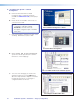
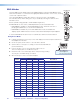
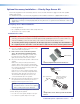
The fully installed system is shown below.
To test that the classroom audio is muted when a
PA system announcement (a page) occurs:
1. Turn the classroom audio on.
2. Speak into the PA system microphone. The
classroom audio should be muted while the PA
page occurs and be restored when the page
ends.
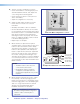
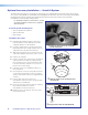
3. If the program fails to mute the classroom audio
during a page, turn the Sensitivity adjustment, on
the front panel of the PVS 305SA IP, clockwise.
4. If the classroom audio is muted without a page
occurring, turn the Sensitivity adjustment
counterclockwise
L R
L R
L R
AUX AUDIO
INPUT 5
LINE OUT
VOICELIFT
RECEIVER
PAGING
SENSOR
DO NOT
GROUND
OR SHORT
SPEAKER
OUTPUTS
1B RGB
1A RGB
2B RGB
2A RGB
3B RGB
/VIDEO
4B RGB
/VIDEO
3A RGB
4A RGB
I
N
P
U
T
S
RS-232 MLC/IR
2/4/8
Ohms
CLASS 2 WIRING
AMPLIFIED AUDIO OUT
VOL/MUTE
TxRx IR 12V
10V 50mA
POWER
US
LISTED
17TT
AUDIO/VIDEO
APPARATUS
®
RGB
VIDEO
OUTPUTS
CONTROL
N15779
12V
5A MAX
LAN 3
LAN 4
LAN 1
LAN 2
Ceiling Mounted
Paging Speaker
Paging System
Priority
Page
Sensor
Classroom
Admin Building
To Classroom
Paging Speakers
Sensor
Output
Paging
Sensor
Input
PVS 305SA IP
PoleVault Switcher
FF 120
Flat Field
Speakers
Typical paging system with PVS 305SA IP switcher.
L
R
L
R
L
R
A
UX AUDI
O
INPUT
5
LINE
O
UT
V
OICELIFT
R
E
C
EIVER
D
O
N
OT
G
ROUND
O
R
S
H
O
R
T
SPEAKER
O
UTPUTS
1
B R
G
B
1
A R
GB
2
B R
G
B
2
A R
G
B
3
B R
G
B
/
VIDEO
4
B R
G
B
/
VIDE
O
3
A R
G
B
4
A R
GB
I
N
P
U
T
S
RS
-232 ML
C/
IR
2
/
4
/
8
O
hms
C
LA
SS
2 WIRIN
G
A
MPLIFIED AUDIO OU
T
V
OL/MUTE
T
x
Rx
IR
1
2
V
1
0
V
5
0m
A
POWE
R
RG
B
V
IDE
O
O
UTPUT
S
C
ONTROL
N1
5
77
9
1
2
V
5A
MAX
LAN
3
LAN
4
LAN
1
LAN
2
PVS 305SA IP
PAGING
SENSOR
Page
Sensor
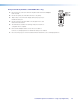
f
Connect the Priority Page Sensor to the
Paging Sensor port on the switcher.
g
Ensure the sensor and wires t completely
inside the junction box before attaching the
cover.
Adjusting sensitivity knob:
Clockwise to increase
Counterclockwise to decrease
PVS 305SA IP
POLEVAULT SWITCHER
PEAK
NORMAL
SIGNAL
AUDIO LEVEL ADJUST
PAGING
SENSOR
SENSITIVITY
VOICELIFT
MIC
PEAK
NORMAL
SIGNAL
PEAK
N
O
RMA
L
SI
G
NAL
A
U
DI
O
LEVEL ADJ
US
T
V
OICELIFT
M
I
C
PEAK
N
O
RMAL
SI
G
NA
L
c
and
d
Sensitivity Knob Adjustment
PoleVault IP Systems • Optional Accessories46