
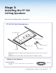
Manual


NOTES:
• The installation must conform to national and local building and electrical codes, and UL requirements.
See the device user guide for details.
• The included power supply MUST NOT be installed above the suspended ceiling, in wall cavities or
similar locations.
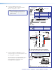
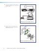
1. — Install the PMK 550 Base Plate
a. Using a 5/32 inch hex wrench, remove the four
cover screws from the center of the PMK 550
and slide the two halves apart. Remove them
from the base plate.
NOTE: If the PoleVault switcher and its power
supply are already installed, go directly to
step 2e.
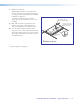
b. To mount the PoleVault switcher, place the
mounting plate, with the raised tabs upwards,
on top of the switcher top and pass the two
supplied 4-40 x 3/16 inch screws down through
the plate holes and into the top of the switcher
(see image at right). Secure the plate but do
not overtighten.
c. Invert the combined plate and switcher and
hook the plate tabs into the PMK 550 base
plate. Secure it to the base plate with two
screws.
NOTE: The switcher should be mounted
on the same side as the base plate’s
pipe collar. The switcher is secured
inverted to the base plate so that when
the plate is turned over and fastened on
the pole, the device will be in the correct
orientation
Use only the supplied screws to avoid
damaging the switcher.
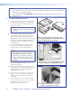
d. Attach the associated power supply with the
supplied plastic ties, by passing the ties through
the appropriate slots and around the power
supply. Tighten until snug.
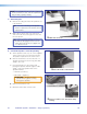
e. Using a 3/32 inch hex wrench loosen the four
pipe collar set screws, and slide the plate up
the pipe until the base plate is touching the
drop ceiling.
f. Level the plate and secure it in place with the
four set screws located on the collar, ensuring
that a minimum of three set screws are
tightened firmly against the pole.
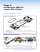
û
Invert and secure the PVS 305SA IP and
ü
the power supply on the PMK 550 base plate.
†
Slide the base plate up onto the pole
and
°
secure with the set screws.
Å
Place the plate (with raised tabs up) on the
top of the PVS 305SA IP and secure with supplied
screws.
û
Hook tabs into base plate.
SIGNAL
5
AUX AUDIO
SENSOR
SENSITIVITY
5
AUX AUDIO
PVS 305SA IP
POLEVAULT SWITCHER
INPUT SELECTION
1
2
PEAK
NORMAL
SIGNAL
CONFIG
3 4
5
AUX AUDIO
AUDIO LEVEL ADJUST
PAGING
SENSOR
SENSITIVITY
VOICELIFT
MIC
PEAK
NORMAL
SIGNAL
INPUT
Å
û
PoleVault IP Systems • Installation — Stage 4 (PMK 550 and PVS 305SA IP)34