
Manual


3. — Install Wall Plates
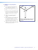
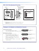
a. Connect the CAT 5 cables to the rear of the
input devices (for RGB devices, connect cable
labeled A to port A and cable B to port B). For
PVT CV D plates connect the single cable to the
device.
b. Run LAN cables (included) to the rear of the
PVT RGB D IP Plus, and connect to the RJ-45
pass-through connectors on the rear panel.
c. With PVT RGB D IP Plus plates, for podcasting
or recording applications, use a three conductor
audio cable and connect the audio return to
the connector marked G (ground wire), R (black
wire), and L (red wire). The other end will be
connected to the Line Out connection on the
PVS 305SA IP switcher.
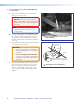
d. If desired wire the IR connection using a
two conductor cable. Wire the ground to G
and signal lead to S. The other end will be
connected to the IR Out port of the
MLC 104 IP Plus controller.
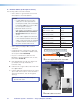
TIP: Before completing the installation of the
PVT RGB D IP Plus wallplate, see EDID
MInder on page 42 for setup and
operating details.
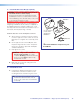
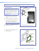
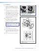
e. Mount each device into the mud ring, using the
supplied screws.
f. Attach the supplied Decora
®
faceplate.
g. Label the Decora plate with the supplied label,
using the appropriate input number. This makes
inputs easier to identify when configuring the
switcher.
h. Repeat steps a through g for other wall plates.
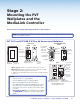
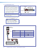
Ñ
Connect the cables to the AV source
input devices at each location.
®
Mount the PVT in the mud ring then
©
attach
the Decora faceplate.
CAT5e
CAT5e
COMPUTER IN
AUDIO
IN OUT
MONITOR OUT
IR OUT
S G
Decora
®
Faceplate
Wall
Mud Ring
Extron
®
PVT RGB D IP Plus
LAN cables
CAT 5 cables
from PoleVault
®
Switcher
COMPUTER IN
AUDIO
IN OUT
MONITOR OUT
IR OUT
S G
CAT5e
CAT5e
PoleVault IP Systems • Installation — Stage 2 (Wallplates and MLC) 25