
Manual

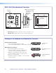

2. — Pull the Cables (at the input locations)
The following cables need to be installed:
• CAT 5 cables for signal transmission from the
AV wall plates to the PVS 305SA IP
NOTES:
• For PVT RGB D IP Plus four CAT 5
cables (two for video input and two
for LAN) are needed, and for PVT RGB
D wall plates, two CAT 5 signal cables
for each input are needed.
• Maximum distance from the
PVS 305SA to the Wallplate is 100 feet.
The optimum distance is between
50 and 75 feet. Minimum distance is
15 feet.
• CAT 5 cables supplied are terminated
to the TIA 568A standard. Other CAT 5
cables can be used if they are TIA 568A
or 568B standards and terminated to
the same standard at both ends.
• CAT 5 cables (included) for MLC network
connection.
• PoleVault switcher communication cable from
the MediaLink controller (MLC PW/RS-232/VC,
50 feet, part number 26-626-50)
• Projector communication cables from the
MediaLink controller (IR Serial Comm, 50 feet,
part number 26-621-50)
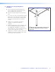
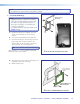
a. Drill cable pathways through any obstructions
(for example, wall caps, fire-breaks, or
horizontal studs).
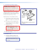
b. Label the CAT 5 signal cables at both ends with
the supplied labels.
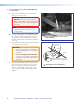
c. Pull the cabling through the wall from the ceiling
space down to the location of the transmitters
and other wall devices, and out through the
openings.
TIP: Secure cables with cable clamps to
provide strain relief.
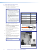
RGB #1A
NOTE:
Fasten the colored section to the cable
first, then wrap the clear section around it.
É
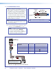
Use the supplied labels for clear cable
identication during installation.
Signal Cable Label color
RGB 1A (Input 1 RGB) Orange
RGB 1 B (Input 1 RGB) Orange
RGB 2A (Input 2 RGB) Yellow
RGB 2B (Input 2 RGB) Yellow
RGB 3A (Input 3 RGB) Magenta
RGB 3B (Input 3 RGB) Magenta
RGB 4A (Input 4 RGB) Light Green
RGB 4B (Input 4 RGB) Light Green
Video 3 (Input 3 Composite Vid) Dark Green
Video 4 (Input 4 Composite Vid) Red
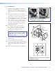
î
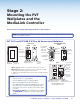
Pull the cables at each location.
PoleVault IP Systems • Installation — Stage 2 (Wallplates and MLC)24