
Manual
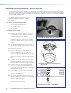

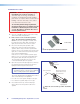

6. Strip 3/16 inches of insulation from each
conductor on the bare wire end of the remaining
blue sensor cable. Do not tin the leads. Feed
the wire into the junction box (clamping it down
if necessary) and connect the wires to the Page
Sensor port captive screw connector (use the +
and - poles) on the rear panel of the PVS 405D.
Polarity need not be observed.
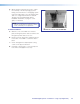
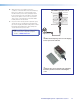
7. If a junction box is being used in a plenum space,
ensure the sensor and all wires fit inside the box
(as shown at right). All cables leaving the box must
be plenum rated. Tighten the cable clamp and
secure the lid to the junction box.
NOTE: To enable the switcher’s paging sensor
port, use the PCS Configuration program,
available at
www.extron.com.
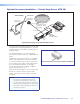
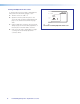
f
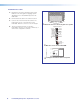
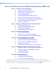
Wire the Priority Page Sensor to the Paging
Sensor port on the switcher.
PVS 405D Paging Sensor Port
AUDIO OUT
PVS 405D
PAGING
SENSOR
R
AUX
VOICELIFT
INPUT 5
+V
R
AU
DI
O
OUT
R
INPUT
5
R
PV
S
40
5D
AUX
VO
I
C
ELIFT
Page Sensor
g
Ensure the sensor and wires fit completely
inside the junction box before attaching the
cover.
PoleVault Digital Systems • Optional Accessories 71