
Manual


iii. Run the cables through the raceway or conduit
to the USFM 100.
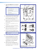
C4. Cable the Switcher.
Connect the cables to the switcher as shown on
pages 43.
NOTE: If using a device other than a PVS 405D (for
example, PVS 305SA IP), refer to the specific device
guide for details.
CAUTION: The WallVault signal transmission
method is specific for PVS 405D switcher
working with PVT digital wallplates.
DO NOT connect the input ports to an MTP,
DTP, or XTP system, or to an LAN or data
transmission system.
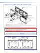
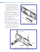
C5. Attach the Boom Arm, Power Supply, and
Projector.
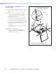
a. Hook the boom arm over the top rail on the
base plate so that the tab on the arm
(see figure below) is against the rail.
Secure the arm at the bottom with the two
supplied (10-32 x 3/8 inch) pan head screws
and washers, and at the top with the single
¼-28 x ¾ inch screw.
USFM 100 Base Plate.
Phillips
Pan Head Screws
Screw
Set Screw
Screws
and Washers
PoleVault Digital Systems • Installation — Stage 4 (USFM 100 and PVS 405D)50