
Manual
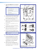

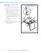

C1. Install the USFM 100 Base Plate.
NOTES:
• It is required to attach the base plate to two wall studs, using a minimum of four securing points
• Drywall KapToggles can be used for holes not aligned with studs.
• Always use the widest spacing of screws and KapToggles.
• The base plate can be installed over an existing electrical outlet.
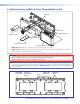
a. Grasp handle, collapse
toggle and insert into wall.
b. Slide plastic washer
down into pilot hole.
c. Cut off handle close to wall.
d. Hand screw in pan head
bolt until 1/8" gap remains.
Toggle Assembly Installation
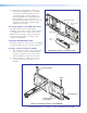
Cutout for
Signal Cable
Access
Marker for
Pilot Hole
Mounting
Holes
Signal Cables
Exiting from
Cutout
Cut out a Cable Access Area
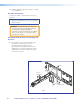
a. To mount the USFM 100 onto non-masonry
walls, at the desired site, use an edge-to-
edge stud finder to locate the center of the wall
studs (wood or steel). Mark each stud location.
Minimum joist size should be 2 by 4 inches.
b. Hold and level the base plate against the wall.
Mark a minimum of four positions (two top, two
bottom) using either the mounting slots or the
keyholes (slots uppermost) that are on the stud
lines. Where applicable, mark the mounting
holes on the wall for drywall toggles.
c. If the cables are to be run behind the wall to the
USFM 100 location, mark the cutout area on
the wall large enough for signal cables.
d. Remove the base plate and set it aside. Cut out
the marked area for cable access.
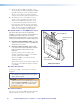
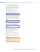
For drywall with wood studs
i. Drill ¼ inch diameter pilot holes at the marked
stud locations.
ii. Align the base plate mounting holes over the
pilot holes and lightly secure with 5/16 inch lag
screws and washers.
iii. Verify level and position, and fully tighten down
all the screws to secure the plate.
For drywall with steel studs
i. Drill a ½ inch (13 mm) hole through the stud at
each of the locations (four recommended).
ii. Insert the supplied toggles through the studs
and lightly secure the plate using the four
supplied (¼-20 x 2 inch) bolts and washers.
iii. Verify level and position, and fully tighten down
all the bolts to secure the plate flush to the wall.
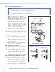
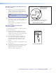
C2. Install the Switcher Onto the Base Plate.
a. Place the mounting plate flat on the switcher
base with the two small raised tabs on top, and
the small securing tab over the front panel. Align
the two mounting holes in the switcher base
with the corresponding holes on the mounting
plate. Secure the plate to the switcher using the
two 4-40 x ¼ inch pan head screws.
PoleVault Digital Systems • Installation — Stage 4 (USFM 100 and PVS 405D)48