
Manual
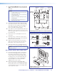


c. Secure the power supply to the right of the
electrical outlet cutout by threading the supplied
tie wraps through the loops on the base plate.
Attach it so the cables are easily and safely
routed to the electrical outlet and switcher alike.
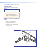
d. An optional ¼ rack, 3 inch deep accessory
device, such as the Extron IPL T S2, can be
installed on the WMK 160 base plate. To do
so, remove the base plate from the wall and
place the device towards the top of the base
plate, align the holes on the base plate and the
device, and secure with the supplied 4-40 x
3/16 inch screws. Replace the base plate.
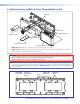
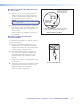
B3. Run the Cables to the WMK 160 Location.
Run signal cables from the proposed PVT input
wallplates, control device location, and the speakers to
the WMK 160 location. Cables can be routed to
WMK 160 either behind the walls, or through a surface
raceway (for example, Wiremold
®
V700 or 2400 series).
a. If running cable behind the walls, run all the
cables from the various locations to the WMK and
through the access cutout.
b. If using a surface raceway, slide the WMK
cover over the base plate, then identify and mark
the most suitable raceway entrance to the
WMK 160.
Run the raceway from the signal source,
speaker, and display locations to the marked
raceway entrance at the WMK.
Remove the WMK cover, and remove the
desired knockout.
Attach the raceway to the wall. Run cables from
the sources and outputs through the raceway
to the WMK.
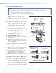
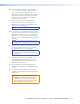
B4. Cable the Switcher.
Connect the cables to the switcher as shown on
pages 43.
NOTE: If using a device other than a PVS 405D
(for example, PVS 305SA IP), refer to the specific
device guide for details.
CAUTION: The WallVault signal transmission
method is specific for PVS 405D switcher working
with PVT wallplates. DO NOT connect the input
ports to an MTP system or to an LAN or data
transmission system.
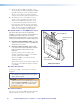
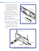
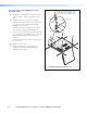
B5. Final Installation.
Place the cover onto the WMK 160 base plate and
tighten down the screws to secure the cover.
Å
Attach the mounting plate to the switcher,
û
fasten the power supply to the base plate,
ü
secure
the base plate to the projector pole,
°
and hook
mounting plate tabs into the base plate.
Raceway Option
2400
V700
Electrical Access
Cutout
Signal Cable
Access Cutout
Cabling Run Options
PoleVault Digital Systems • Installation — Stage 4 (WMK 160 and PVS 405D)46