
Manual
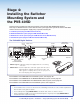


B. WallVault System (WMK 160 Wall Mount Kit)
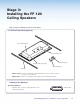
B1. Install the WMK 160 Base Plate
NOTES:
• For masonry wall use steps a to e.
• For non-masonry walls use steps f to j.
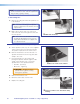
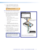
a. To mount the WMK 160 onto masonry
walls, hold the base against the wall, level it,
and mark the positions of four slotted mounting
holes (indicated by + marks in the figure at
right). Set the base plate aside.
b. Using a masonry drill bit, drill 1¾ inch (4.4 cm)
deep pilot holes at the marked locations.
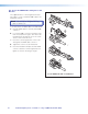
c. Screw in ¼ x 1¾ inch masonry screws (not
supplied) until a gap of about 3/8 inch (9 mm)
remains between the wall and the screw heads.
d. Align the slotted mounting holes of the base
plate over the installed screws, then slide the
plate down so the screws fit into the slots.
e. Verify level and position and tighten all the
screws to secure the plate flush to the wall.
Proceed to step B2.
• Where it goes: Installs onto a wall close to the projector.
• What it does: Supports and hides from view the installed PVS 405D switcher, power supply, and any
installed optional accessories.
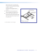
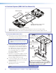
(2) #14 x 1 3/4"
Self-tapping
Metal/Wood Screws
(4) 1/4-20 x 2"
Pan Head Bolts
(4) 1/4" KapToggle
®
Assemblies
(4) Cover Screws
(1) PoleVault Switcher
Mounting Plate
(1) WMK 160 Cover
(1) WMK 160 Base Plate
(
2
)
#14
Se
l
M
et
(
4
)
(4) 1
/
4
"
Ass
(4)
Co
v
(1) P
o
M
o
K
160 Base P
lat
e
e
(
1
)
WM
K
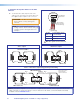
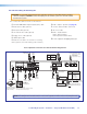
Cutout for
Electical Outlet
Level
Cutout for Signal Cable Access
Marker for
Pilot Hole
WMK 160
Base Plate
Mounting
Holes
Mounting the base plate on a masonry wall.
PoleVault Digital Systems • Installation — Stage 4 (WMK 160 and PVS 405D)44