
Manual
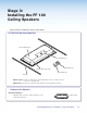


A4. Finish Installing the Mounting Kit.
CAUTION: The PoleVault signal transmission method is specific for PVS 405D switcher working
with PVT wallplates. DO NOT connect the input ports to an MTP system or to an LAN or data
transmission system.
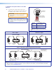
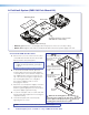
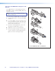
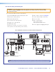
a. Connect the cables as follows to the switcher:
LR
DO NOT
GROUND
OR SHORT
SPEAKER
OUTPUTS
4/8
Ω
3A MAX
POWER
12V
HDMI
1/2
SIG LINKSIG LINK
3/4
INPUTS OUTPUT AUDIO OUT
PVS 405D
AMPLIFIED AUDIO OUT
PAGING
SENSOR
PVT IN PVT IN
L
R
AUX OVER PVT REMOTE
VOICELIFT
LAN 1 LAN 2 LAN 3
INPUT 5
+V
L
R
RS-232
Tx Rx
IR
SG G
HDMI Output
to Display Device
HDMI
Connector
Aux Audio
Input 5
Audio Output to Speakers
Red Positive (+)
Black Negative (-)
Speaker
wire color
PVS terminal
(left and right)
Line Out
Output (Audio)
Paging
Sensor
Aux
Input
Supplied PVS Switcher
Exter
nal Power Supply
(12 VDC, 4 A max.
)
3-port 10/100 Ethernet Switch
Connect to ports as follows:
1. TCP/IP network
2. MLC controller
3. Optional network device
5
7
12
Power Connector
HDMI/RGB
PVT SW HDMI RGB D
HDMI or RGB video/audio, Inputs1/2 and 3/4
1 STP cable with RJ-45 connectors
VGA IN
AUDIO
IN OUT
LOCAL OUT
AUDIO IN
HDMI IN
IR OUT
S
G
6 2 3
VoiceLift
Receiver
4
IR control
10
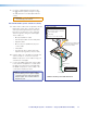
MLC 104 IP Plus
RS-232 input
White Tx on RS-232 port
Violet Rx on RS-232 port
Drain wire Ground (G)
Black Power Supply (–)
Red Power Supply (+)
MLC
wire color
To PVS terminal
9
11
8
+V
SG
MLC 104 IP Plus right side
panel MLS and Power ports
RS-232 12V
MLS PWR
AB
Rx
Tx
GROUND
GROUND
+12V IN
B
Ground
+12 VDC input
To Supplied
PVS Switcher
Power Supply
(12 VDC, 4 A max.)
NOTE: If you use cable that has
a drain wire, tie the drain wire
to ground at both ends.
NOTE: You must connect
a ground wire between
the MLC and PVS.
Ground (Gnd)
Transmit (Tx)
B
Receive (Rx)
A
Transmit (Tx)
Receive (Rx)
B
A
1
G
a PVT SW HDMI RGB D Input wall plate (STP) cable
b Audio input 5 cable (optional)
c Aux input cable (optional)
d VoiceLift Receiver cable (optional)
e Paging sensor cable (optional)
f HDMI output cable
g Audio line out cable to an assistive or recording
device (optional, see audio warning card for details)
h Audio output to speakers (see page 38)
i Control cable from MLC 104 IP Plus
j IR control cable
k LAN 1: TCP/IP Network
LAN 2: MLC Controller
LAN 3 Optional network device
l Power supply. Do not apply power yet.
Your completed connections should look like the image below.
NOTE: The cabling of the PoleVault Switcher is the same regardless of which switcher mounting kit used.
PoleVault Digital Systems • Installation — Stage 4 (PMK 560 and PVS 405D) 43