
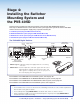
Manual
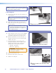
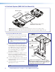


f. Hook the combined plate and switcher into
the PMK 560 base plate (see figure on page
40,
°
). Secure it to the base plate with two
screws.
ATTENTION: Use only supplied screws to
avoid damaging the switcher.
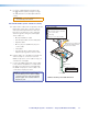
A2. Pull the Cables (at the switcher location).
a. Gather all the cables from the speakers, AV wall
plates, MLC 104 IP Plus controller, network,
and any installed optional devices that have
been run to the switcher location. Pull them
down through the ceiling hole and the pipe.
These cables are:
• MLC power/RS-232 cable
• STP AV input cables from the wall plates
• Speaker cables
• MLC to projector (IR/RS-232 projector
control) cable
• LAN cables
• Any optional device cables (Aux audio
input Priority Page Sensor Kit, VoiceLift)
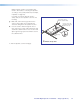
b. Pull the cables out of the pipe slot towards the
switcher, ready for connection. Leave the
IR/RS-232 projector control cable to hang out
of the bottom of the pipe.
c. Connect the HDMI output video signal cables
to the switcher and pull the loose ends down
the pipe so that they hang out the pipe with
the IR/RS-232 projector control cable, to be
connected to the projector later.
NOTE: Do not thread any high voltage
power cabling, such as power supply
or projector power cords, through the
projector pipe. This violates National
Electrical Code.
L R
DO NOT
GR
O
UND
OR SHORT
SPEAKER
OUTPUTS
4/8
Ω
3
A MAX
POWE
R
12V
HDMI
1/2
SIG
LINK
SIG
L
INK
3/4
INPUTS
OUTPUT
AUDIO OUT
PVS 405SA IP
AMPLIFIED AUDIO OUT
PAGING
SENSOR
PVT IN
PVT IN
L
R
AUX
OVER PVT
REMOTE
VOICELIFT
LAN 1
LAN 2
LAN
3
INPUT 5
+V
L
R
RS-232
TxRx
IR
S
G G
1
1
4
2
3
3
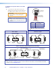
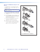
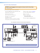
Optional accessory cables fr
om
the VoiceLift and Page Sensor,
may also be included.
1
2
3
FF 120 speaker cables
MLC 104 IP Plus switcher control cable
AV wall plate cables, STP
Cables to PVS 405D
LAN cable(s)
4
5
6
To Projector
HDMI cable
6
Cable Access
Slot
Cables to Projector
5
6
4
1
3
2
IR projector control cable (from MLC)
5
Switcher and Projector Cable Overview
PoleVault Digital Systems • Installation — Stage 4 (PMK 560 and PVS 405D) 41