
Manual
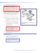


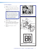


b. Connect the IR/RS-232 projector
communication cable as shown for either
RS-232 or IR projector control
NOTE: Some projectors require NULL
connection wiring, which inverts the Tx
and Rx connections. See the projector
guide for details.
IR control for a connected input device such as
a Blu-ray player can be made through the PVT
wallplate (see the figure at step 4d).
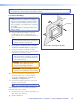
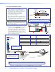
c. Connect a network cable (CAT 5, 5e, or 6
straight through) from the PVS 405D to the
RJ-45 LAN jack on the MLC.
The switcher acts as a 3-port Ethernet switch,
when connected to the LAN.
á
Connect the MLC to the projector with an
RS-232 cable or IR emitter cable, as appropriate.
ó
Connect to the LAN using a CATx cable.
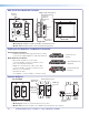
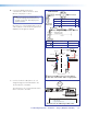
Terminal RS-232 Cable color Pin
Tx White 2
Rx Violet 3
Ground
Shield 5
Terminal IR/RS-232 Cable color IR Cable color
Ground Black Black
IR Signal Red White/Black
RedBlack
Projector
MLC IR/RS-232
Comm Cable
IR Emitter
Connecting IR Cable
White
(or striped)
Black
Red
Blac
k
9-Pin Female
White
Violet
Shield
MLC 104 IP Plus
Connecting RS-232 Cable
Projector
GROUND
IR OUT
Tx
Rx
DISPLAY
RS-232/IR
GROUND
IR OUT
Tx
Rx
DISPLAY
RS-232/IR
NOTE: Red and black
not used.
NOTE: White, violet, and
shield not used.
LR
DO NOT
GROUND
OR SHORT
SPEAKER
OUTPUTS
4/8
Ω
3A MAX
POWER
12V
HDMI
1/2
SIGLINKSIG LINK
3/4
INPUTS OUTPUT AUDIO OUT
PVS 405D
AMPLIFIED AUDIO OUT
PAGING
SENSOR
PVT IN PVT IN
L
R
AUX OVER PVT REMOTE
VOICELIFT
LAN 1LAN 2LAN 3
INPUT 5
+V
L
R
RS-232
Tx Rx
IR
SG G
1
2
3
GROUND
+12V OUT
CM
GROUND
IR OUT
GROUND
SCP
GROUND
Tx
Rx
DISPLAY
RS-232/IR
A B C D E
COMM LINK
LAN
PRESS TAB WITH
TWEEKER TO REMOVE
A B
MLS
RS-232
POWER
12V
DIGITAL
I/O
IR IN
Tx
GROUND
Rx
+12V IN
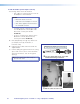
MLC 104 IP Plus Right Side Panel
CAT 5, 5e or 6 Cable
PVS 405D
NOTE: Connect to the PVS 405D Ethernet ports as follows:
1. TCP/IP network
2. MLC controller
3. Optional Network Device
TCP/IP
Network
PoleVault Digital Systems • Installation — Stage 2 (Wallplates and MLC) 33