
Manual
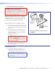


3. Install the Wallplates.
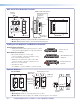
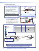
a. Connect the cables to the rear of the input
devices.
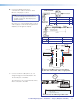
b. If desired, wire an IR emitter to the unit using a
two conductor cable. Wire the ground to G and
signal lead to S. IR signals are transmitted over
the STP cables.
NOTE: For podcasting or recording
applications, use a three conductor audio
cable and connect the audio return to
the connector marked G (ground wire),
R (black wire), and L (red wire). The other
end will be connected to the “Line Out”
connection on the PVS 405D switcher.
This option is available only with
PVT SW HDMI RGB D wallplates.
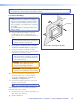
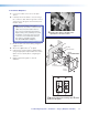
c. Mount the device into the mud ring, using the
supplied screws.
d. Attach the supplied Decora
®
faceplate.
e. Label the Decora plate with the supplied label,
using the appropriate input number. This makes
inputs easier to identify when configuring the
switcher.
f. Repeat steps a through e for other AV
wallplates.
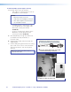
Ñ
Connect the cables to the AV source
input devices at each location.
ñ
Mount the PVT in the mud ring then
õ
attach
the Decora faceplate.
VGA IN
AUDIO
IN OUT
LOCAL OUT
S G
HDMI IN
AUDIO IN
IR OUT
S
G
Decora
®
Faceplate
Wall
Mud Ring
Extron
PVT SW HDMI RGB D
STP Cable
from PoleVault
®
Switcher
Audio Input Cable
VGA IN
AUDIO
IN OUT
LOCAL OUT
AUDIO IN
HDMI IN
IR OUT
G
S
PoleVault Digital Systems • Installation — Stage 2 (Wallplates and MLC) 31