
Manual
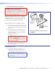


2. Pull the Cables (at the input locations)
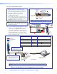
The following cables need to be installed:
• STP cables for signal transmission from the
AV wallplates to the PVS 405D
NOTES:
• Maximum distance from the
PVS 405D to the Wallplate is 150 feet.
• STP cables supplied are terminated to
the TIA 568B standard.
• PoleVault switcher communication cable
from the MediaLink controller (MLC PW/
RS-232/VC, 50 feet, part number
26-626-50)
• Projector communication cables from the
MediaLink controller (IR Serial Comm,
50 feet, part number 26-621-50)
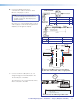
a. Drill cable pathways through any obstructions
(for example, wall caps, fire-breaks, or
horizontal studs).
b. Label the signal cables at both ends with the
supplied labels.
c. Pull the cabling through the wall from the ceiling
space down to the location of the transmitters
and other wall devices, and out through the
openings.
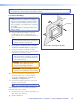
TIP: Secure cables with cable clamps to
provide strain relief.
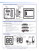
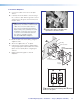
INPUT 1/2
NOTE:
Fasten the WHITE section to the cable
first, then wrap the clear section around it.
É
Use the supplied labels for clear cable
identification during installation.
î
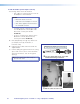
Pull the cables at each location.
PoleVault Digital Systems • Installation — Stage 2 (Wallplates and MLC)30