
Manual


NOTE: The installation must conform to national and local building and electrical codes, and
UL requirements. See the device user guides for details.
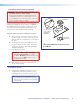
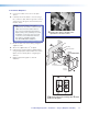
1. Install the Mud Rings.
NOTE: These devices can be installed using the
supplied mud ring or a wall box. If installing a
box, allow enough depth for the plate and the
cables. The box should be at least 2.5 inches
(6.4 cm) deep to accommodate the connectors
and cables.
If a suitable wall box is already installed, follow
step 2 onwards.
a. Using an appropriate template or the PVT
mounting enclosure as a guide, with a soft
pencil, mark the area of the wall that will be cut
out.
NOTE: If installing a metal junction box,
check with the manufacturer of the box for
specific installation requirements.
b. Use a jigsaw or small hand saw to carefully
cut away the material within the marked area.
c. If using a mud ring in a wall with insulation
inside, remove at least 6 inches of the insulation
in all directions around the cutout.
NOTE: If a wall stud interferes with
removing 6 inches of insulation around the
cutout, remove the insulation between the
cutout and wall stud.
CAUTION: Risk of personal injury. Smooth
the edges of the opening to avoid
personal injury during installation.
ATTENTION: Smooth the edges of the
opening to avoid damage to the mounting.
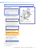
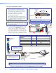
d. Insert the mud ring into the opening. The
mud ring locking arms should fit easily into
the opening. If needed, use a saw, file, or
sandpaper to enlarge the hole.
e. Rotate the mud ring locking arms and secure
with the screws provided.
TIP: Use a level when fitting the mud ring.
Repeat steps a to c for each additional input wall
plate that needs to be installed.
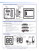
f. At the desired location mark the opening for the
MLC 104 IP Plus mud ring.
g. Repeat steps b to e.
û
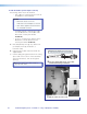
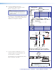
Insert the mud ring into the wall.
4.00"
3.75"
Wall
Mud Ring
PoleVault Digital Systems • Installation — Stage 2 (Wallplates and MLC) 29