
Manual


CONFIG
DISPLAY
VOLUME
MLC 104 IP PLUS
ON
VCR
DVD
PC
OFF
1
2
3
4
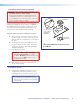
Mounting
screws (4)
1
2
3
GROUND
+12V OUT
CM
GROUND
IR OUT
GROUND
SCP
GROUND
Tx
Rx
DISPLAY
RS-232/IR
A B C D E
COMM LINK
LAN
PRESS TAB WITH
TWEEKER TO REMOVE
A B
MLS
RS-232
POWER
12V
DIGITAL
I/O
IR IN
Tx
GROUND
Rx
+12V IN
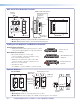
Right Side
Ethernet
port
Display/RS-232/IR
Comm. Link
Digital I/O,
MLS/RS-232
Power
RUN
100
00-05-A6-01-6B-F5
Location of
MAC address
Rear View
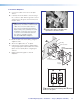
Captive screw connectors for:
MLS 104 IP Plus MediaLink Controller
• Where it goes: Installs in a wall at a location convenient to user.
• What it does: Provides remote control of switcher and projector.
MLC PW/RS-232, 50 ft
26-626-50
IR Serial Comm, 50 ft
26-621-50
STP201P cable, 35 ft
26-696-35
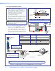
Cabling for the Wallplates and MediaLink Controller
PVT transmitter installation
• Sheilded twisted pair (STP) signal transmission cables
(connects PVT input wallplates to PVS 405D switcher)
MLC 104 IP Plus installation
• MLC power and RS-232 control cable
(connects the MLC controller to the MLC control
port on the PVS 405D switcher)
• IR/RS-232 communications cable control cable
(connects the MLC controller to the projector via
RS-232 or to an IR emitter)
• LAN network cable
(not supplied - connects the MLC controller to LAN)
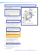
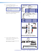
Optional Wallplate
• Where it goes: Installs in a wall near input source location.
• What it does: Transmits an input source HDMI and audio signals to the switcher.
AUDIO IN
HDMI IN
IR OUT
G
S
AUDIO IN
HDMI IN
AUDIO IN
HDMI IN
IR OUT
G
S
AUDIO IN
HDMI IN
PVT SW HDMI D
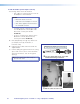
Decora
Faceplate
Mounting
Screws (4)
Audio Input Connector
IR Output
Audio and
HDMI input
Connectors
Signal/Power
Status LED
HDMI Input
Connector
PVT Output Port
(at Rear)
PVT SW HDMI D
SIG LINK
PVT OUT
PoleVault Digital Systems • Installation — Stage 2 (Wallplates and MLC)28