Installation Guide PoleVault System PoleVault Digital Switcher Systems featuring the PVS 405D Switcher Includes installation details for the PoleVault (PMK 560), WallVault (WMK 160 and USFM 100), and PlenumVault (PVM 220) Mounting Kits. LE: ILAB tem A V ® ys OA ALS eVault S eo. l . Vid Po The tallation tron.com x s In ww.e at w t i View 68-2380-01 Rev.
Safety Instructions Safety Instructions • English WARNING: This symbol, , when used on the product, is intended to alert the user of the presence of uninsulated dangerous voltage within the product’s enclosure that may present a risk of electric shock. ATTENTION: This symbol, , when used on the product, is intended to alert the user of important operating and maintenance (servicing) instructions in the literature provided with the equipment.
FCC Class A Notice This equipment has been tested and found to comply with the limits for a Class A digital device, pursuant to part 15 of the FCC rules. The Class A limits provide reasonable protection against harmful interference when the equipment is operated in a commercial environment. This equipment generates, uses, and can radiate radio frequency energy and, if not installed and used in accordance with the instruction manual, may cause harmful interference to radio communications.
Conventions Used in this Guide Notifications The following notifications are used in this guide: DANGER: A danger indicates a situation that will result in death or severe injury. WARNING: A warning indicates a situation that has the potential to result in death or severe injury. CAUTION: A caution indicates a situation that may result in minor injury. ATTENTION: Attention indicates a situation that may damage or destroy the product or associated equipment.
Contents Introduction............................................................ 1 Overview............................................................. 1 The Digital PoleVault, WallVault, and PlenumVault Systems......................................... 1 Specifications Availability..................................... 1 Application Diagram............................................ 2 Before You Begin — Planning the Installation....... 3 Americans with Disabilities Act (ADA) Compliance....................
B4. Cable the switcher.................................. 46 B5. Final Installation....................................... 46 C. WallVault System (USFM 100 Short Throw Wall Mount Kit)....... 47 C1. Install the USFM 100 Base Plate............. 48 For drywall with wood studs.......................... 48 For drywall with steel studs............................ 48 C2. Install the switcher onto the Base Plate... 48 C3. Run the cables to the USFM 100 location.................................
Introduction Overview This guide covers the installation of the Extron PoleVault Digital System, and also the installation methods for each type of WallVault and PlenumVault enclosure. NOTE: PoleVault, WallVault, and PlenumVault Digital systems use the same digital PVS switcher, input source AV devices, control device, and ceiling speakers. However, the systems have different mounting enclosures, (PMK 560, USFM 100, WMK 160, and PVM 220), depending on the system type.
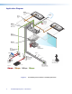
Application Diagram Extron FF 120 Flat Field Speakers - 1 Pair TCP/IP Network Extron SPK 18 - 35' Cable Ethernet Extron VLR 102 VoiceLift Receiver Extron PCM 340 Projector Drop Ceiling Mount with Adjustable Pole Extron PMK 560 Easy Installation Pole Mount Kit Y AL ITIVIT SENS SIGN AL SIGN AUX 4 1 2 Extron PVS 405D PoleVault Switcher Extron UPB 25 Universal Projector Mounting Bracket Extron PVT SW HDMI RGB D HDMI, RGB & Audio Input Wallplate IN AU DI RS-232 to Switcher O OU T VG A
Before You Begin — Planning the Installation Before installation is started, you must consider several major factors to ensure that the installation process is as smooth and trouble free as possible, and so that the final finished project meets the needs of the customers, users, audiences, and installer. The installation considerations on the following pages, though not comprehensive, should be consulted to help ensure that key installation aspects have been considered.
• Ceiling and wall type (important in assessing the hardware needed) • Ceiling type: dropped, spline, hard lid, and similar. Structural type (wood, concrete, trusses), plenum or non-plenum • Wall type: drywall, cement, brick. WARNING: Structural ceiling failure could cause death serious injury or death. Check the structural ceiling to ensure that it can handle a load four times the weight of the final setup.
Location of MediaLink Controller and Wall Plates • Forward and side reach (for full details refer to a copy of ADA Standards for Accessible Design, Sections 307 and 308, for ADA requirements).
Inventory — PoleVault Digital System NOTE: The PoleVault Digital System inventory is shown on this and the next page. For WallVault and PlenumVault Digital Systems, see the inventory lists on pages 8 to 11. The PoleVault Digital System (PVS xxx) ships in two boxes. The larger box contain the devices and hardware, individually boxed and labeled. The smaller box contains only the FF 120 speakers. Carefully check all the received items against the lists on this and the next page..
Kits • PVS 200D (part number 42-207-03) includes one PVT SW HDMI D • PVS 400D (part number 42-208-03) includes one PVT SW HDMI RGB D and one PVT SW HDMI D. NOTE: If any items in the PoleVault Digital System boxes are damaged or missing, contact the Extron Technical Support Hotline (see rear cover for contact numbers).
Inventory — WallVault Systems (USFM 100) Extron USFM 100 Boom Arm Base Plate Device Mounting Plate Arm Cover (top) Arm Cover (front) Arm Cover (buttom) Plastic Enclosure Cover Figure 5.
Inventory — WallVault Systems (WMK 160) (4) 1/4" KapToggle® Assemblies Ass (4) 1/4-20 x 2" Pan Head Bolts (2) #14 x 1 3/4" Self-tapping Sel Metal/Wood Met Screws (4) Cov Cover Screws (1) WMK K 160 Base Plate e (1) Po PoleVault Switcher Mo Mounting Plate (1) WMK 160 Cover Figure 6.
Inventory — PlenumVault Systems (PVM 220) T PAGIN SENS JUS SENS AD EL PEAK NORMA LEV SIGNAL L VOICE LIFT DIO PEAK SIGNAL L AU 3 1 5 X AU FIG R CON SEL EC T 2 4 IN PU TS AU DIO INPU T NORMA IT IV IT Y G OR POL PV EVA S 40 ULT 5S SW A ITC IP HER E Figure 7.
Inventory — PlenumVault Systems (PVM 220) 42-230-03 PLS 210D Part Number Description Quantity 26-621-50 MLC IR cable, 50 ft 1 26-626-50 MLC PW/RS-232 cable, 50 ft 1 26-627-35 Speaker cable, 35 ft 2 26-692-15 HDMI Plenum M-M cable, 15 ft 1 26-696-35 STP 201P cable, 35 ft 1 42-120-03 FF 120 speakers 1 pair 60-818-03 MLC 104 IP Plus 1 60-1335-03 PVT SW HDMI RGB D 1 70-1072-01 KTS, PVM 220/PVS 405D/PS 1 Part Number Description Quantity 26-621-50 MLC IR cable, 50 ft 1 26-626-
Items Not Included The following items are not included in the systems. However, input and display devices are essential parts of the system, and at any installation they may vary depending on their use. This list suggests various devices that may be used.
Optional Items The optional Extron products suggested below can be added to or substituted for items in the standard Digital PoleVault System. Some of these items may also be suitable for the Digital WallVault or PlenumVault Sytems.
14 PoleVault Digital Systems • Introduction
Installation Overview This section outlines the basic steps for installing the PoleVault System. An outline and checklist of the stages (Stages One through Five), listing the relevant steps within each stage, is given on pages 16 and the rear cover. A fully detailed description of these steps is given in the five corresponding sections. Carefully check inventory of PoleVault System packages, input and output devices, any optional accessories, and installation hardware before commencing.
Outline of Installation Steps for PoleVault Digital Systems Stage 1 — Install the Screen and Projector c Mark the screen location (page 18). c Install projector to verify location (page 18). c Verify the image location (page 21). c Cut the ceiling tile (page 22). c Preliminary safety hardware installation (page 22). c Finish projector drop ceiling mount installation (page 23). c Secure the projector drop ceiling mount to the ceiling (page 24).
Stage 1: Installing the Screen and Projector Stage 1 Involves installing the three pieces of hardware shown below. PCM 340 Projector Drop Ceiling Mount a • • Where it goes: Attaches to a structural ceiling, rests on the suspended ceiling. 1-gang and 2-gang Accessory Mounting Points (Power Sockets) 1 What it does: Holds the slotted pipe, PoleVault pole mount kit (PMK 560), and projector.
1. Mark Screen Location. TIPS: When marking the location of screens, devices, or the site for installing transmitters and MediaLink control devices, use painters tape to avoid wall surface damage. • Ä Mark the screen location. When marking the center line of the screen, where possible, keep it aligned with the center of the ceiling tile. This makes the projector installation and alignment easier. • a. Mark the center line and the outer edges of the screen. b.
d. Using a 3/32 inch hex wrench, back out the set screws on the top portion of the adjuster plate (see a in the image below) of the UPB 25. Screw the plate onto the base of the pipe. Align it so the security flange is at the rear a Set Screws (2) Loosen the four adjuster plate locking screws and slide the adjuster plate away from the projector bracket. Adjuster Plate b Pivot Screws Projector Bracket ï Screw the adjuster plate onto the base of the pipe.
Pivot the arms so that they extend towards the center of the projector (see the figure at right). Adjust the arms as needed for your projector model. vi. NOTE: Avoid overlapping the arms where possible. Washer With the security flange towards the rear of the projector, place the projector bracket on top of the arms and adjust for slot alignment. vii. • vi. Pivot arms towards center of projector.
x. Check for stress on the arms. To do this loosen the mounting screws (do not remove). If the arm or the barrel lifts, this indicates stress on the arm. Adjust the height of the threaded barrels to reduce or eliminate any torque or stress that might be caused by crossed arms or by projector mounting points with differing heights. It is important to keep the arms level and as close (low) to the projector base as possible. Check that the projector weight is still as evenly distributed as possible.
4. Cut the Ceiling Tile. a. Mark the location of the PCM 340 on the T-frame. This aids putting it back in the correct location when the tile is replaced. TIP: Mark the screen direction on back of the tile (for example with an arrow or “to front”) to help orientation of tile when replacing it after cutting b. Measure the distances X and Y (see the figure at right) from the inner vertical section of the front and left T-frame runners to the center of the Pipe Adapter Plate.
6. Finish Projector Drop Ceiling Mount Installation. a. Detach the projector bracket and projector from the adjuster plate. DO NOT remove the projector bracket from the projector. b. Unscrew the adjuster plate from the mounting pole. c. Loosen the pipe adapter set screws on the PCM 340 and the pipe location screw and remove the mounting pole, then loosen the T-frame securing screws and remove the PCM 340 from its marked location. d.
7. Secure the Projector Drop Ceiling Mount to the Ceiling. a. Attach the four turnbuckles to the base plate, one at each corner. WARNING: May result in serious injury. DO NOT rest or lean on the mounting plate or suspended ceiling when attaching turnbuckles, tie wire, or when drilling into the ceiling. NOTE: For safest installation, insert the turnbuckle from the outside so that it hooks inwards b.
8. Install the Electrical Box (If required). WARNING: Improper installation may result in electrical shock or serious injury. All electrical installation should be performed by qualified personnel in accordance with local and national building codes, fire and safety codes, and local and national electrical codes.
26 PoleVault Digital Systems • Installation — Stage 1 (Screen and Projector)
Stage 2: Mounting the PVT Wallplate and the MediaLink Controller Stage 2 Involves installing and cabling the devices shown below. NOTE: The installation must conform to national and local electrical codes and UL requirements. See the device user guide for details.
MLS 104 IP Plus MediaLink Controller Captive screw connectors for: Mounting screws (4) Display/RS-232/IR Comm.
NOTE: The installation must conform to national and local building and electrical codes, and UL requirements. See the device user guides for details. 1. Install the Mud Rings. NOTE: These devices can be installed using the supplied mud ring or a wall box. If installing a box, allow enough depth for the plate and the cables. The box should be at least 2.5 inches (6.4 cm) deep to accommodate the connectors and cables. If a suitable wall box is already installed, follow step 2 onwards. a.
2. Pull the Cables (at the input locations) The following cables need to be installed: • STP cables for signal transmission from the AV wallplates to the PVS 405D NOTES: • Maximum distance from the PVS 405D to the Wallplate is 150 feet. • STP cables supplied are terminated to the TIA 568B standard.
3. Install the Wallplates. a. Connect the cables to the rear of the input devices. b. If desired, wire an IR emitter to the unit using a two conductor cable. Wire the ground to G and signal lead to S. IR signals are transmitted over the STP cables. NOTE: For podcasting or recording applications, use a three conductor audio cable and connect the audio return to the connector marked G (ground wire), R (black wire), and L (red wire).
4. Install the MediaLink Controller. TIP: Before cabling and installing the MLC 104 IP Plus, locate the device MAC address printed on a label on the bottom of the controller. Write down the 12 character alphanumeric address, (for example, 00-05-A6-03-9G-H4) and use when configuring the IP address. When cabling, the length of exposed wire is critical to avoid transmission problems. Ensure the lengths given here are adhered to when stripping the cables for connection. Wire Bared 3/16" (5 mm) Max.
b. Connect the IR/RS-232 projector communication cable as shown for either RS-232 or IR projector control NOTE: Some projectors require NULL connection wiring, which inverts the Tx and Rx connections. See the projector guide for details. Terminal RS-232 Cable color Tx IR control for a connected input device such as a Blu-ray player can be made through the PVT wallplate (see the figure at step 4d).
d. The connections between the MLC 104 IP Plus and the PVS 405D switcher should look like the figure below.
Stage 3: Installing the FF 120 Ceiling Speakers Stage 3 Involves installing the devices shown below. FF 120 Flat Field Ceiling Speakers FF 120 Speaker (2) Terminal Cover Cable Clamps (2) Seismic Tabs (3 per side) Anchor Rings (2) T-rails (2) • Where it goes: Installs in ceiling tiles at a predetermined location for best acoustics. Connects to the switcher. • What it does: Receives and outputs audio signal from the PVS 405D switcher.
NOTE: The installation must conform to national and local electrical codes, and UL requirements. See the device guide for details. 1. Cut Ceiling Tile. a. Remove the ceiling tiles where the speakers are to be installed. TIP: For ease of working on the speaker when it is replaced on the T-frame, remove adjacent tiles. b. Mark a line 12 inches from one of the short sides of the tile and cut along the line. Discard the short portion. Å Mark and cut the tile.
Repeat steps 1 and 2 for each speaker that needs to be installed, connecting the speakers according to the system preferred (for example, in parallel, see page 38). If you wish to install an optional seismic/ safety cable, at each speaker location do the following: Anchor this end to a lag eye bolt screwed into the structural ceiling. g. Mark, drill, and install a lag eye bolt for the seismic safety cables (not included) in the structural ceiling above the speaker location. h.
3. Terminate the Speaker Cable for the PVS Switcher. a. To terminate the cable, strip the end of the cable 0.2 inch (5 mm) and secure the wires into the supplied 4-pole captive screw connector. AMPLIFIED OUTPUTS 4/8 Ohms L R ATTENTION: DO NOT short the speaker wires together as it may damage the switcher. PVS Switcher Rear Panel 4-pole Captive Screw Connector (viewed from top) NOTE: The correct speaker impedance loading must be observed when setting up a speaker system. See figures below for examples.
Stage 4: Installing the Switcher Mounting System and the PVS 405D Stage 4 Involves installing the switcher mounting system and the PVS 405D Digital Switcher. This stage is divided into four sections based on the system type. Each system mounts the PVS 405D switcher and associated power supply using a specific mounting kit. A. PoleVault System (using the PMK 560 Pole Mount Kit) B. WallVault Wall Mount System (using the WMK 160 Wall Mount Kit) C.
A. PoleVault System (PMK 560 Pole Mount Kit) Mounting Plate Base Plate To open, remove 4 cover screws and slide the covers away. PMK Covers (2) • Where it goes: Attaches to slotted pipe, above the projector and close to the drop ceiling. • What it does: Supports and hides the installed PVS 405D switcher and power supply from view. A1. Install the PMK 560 Base Plate. a. Remove the four cover screws from the center of the PMK 560 and slide the two halves apart. Remove them from the base plate.
f. Hook the combined plate and switcher into the PMK 560 base plate (see figure on page 40, ). Secure it to the base plate with two screws. ° ATTENTION: Use only supplied screws to avoid damaging the switcher. A2. Pull the Cables (at the switcher location). a. Gather all the cables from the speakers, AV wall plates, MLC 104 IP Plus controller, network, and any installed optional devices that have been run to the switcher location. Pull them down through the ceiling hole and the pipe.
A3. Secure the HDMI Cables Using the LockIt Bracket. The supplied Extron LockIt lacing bracket makes it possible to secure a standard HDMI cable to the PVS 405D switcher. b NOTE: The tie wrap can be tightened using pliers or similar tools. a To securely fasten an HDMI cable to the PVS 405D: a. Plug the HDMI cable into the rear panel HDMI connector. b. Loosen the HDMI connection mounting screw from the rear panel enough to allow the LockIt lacing bracket to be placed over it.
A4. Finish Installing the Mounting Kit. CAUTION: The PoleVault signal transmission method is specific for PVS 405D switcher working with PVT wallplates. DO NOT connect the input ports to an MTP system or to an LAN or data transmission system. a.
B. WallVault System (WMK 160 Wall Mount Kit) (4) 1/4" KapToggle® Assemblies Ass (4) 1/4-20 x 2" Pan Head Bolts (2) #14 x 1 3/4" Self-tapping Sel Metal/Wood Screws Met (4) Cov Cover Screws (1) WMK K 160 Base Plate e (1) Po PoleVault Switcher Mounting Plate Mo (1) WMK 160 Cover • Where it goes: Installs onto a wall close to the projector. • What it does: Supports and hides from view the installed PVS 405D switcher, power supply, and any installed optional accessories. B1.
f. To mount the WMK 160 onto non-masonry walls, at the desired site, locate and mark the wall studs. Mounting Holes Cutout for Electrical Outlet Wall Studs Cutout for Signal Cable Access Level Marker for Pilot Hole NOTES: • For ideal installation secure the base plate to at least one wall stud • Drywall KapToggles can be used for holes not aligned with studs. • Always use the widest spacing of screws and KapToggles. • The base plate can be installed over an existing electrical outlet.
c. Secure the power supply to the right of the electrical outlet cutout by threading the supplied tie wraps through the loops on the base plate. Attach it so the cables are easily and safely routed to the electrical outlet and switcher alike. d. An optional ¼ rack, 3 inch deep accessory device, such as the Extron IPL T S2, can be installed on the WMK 160 base plate.
C. WallVault System (USFM 100 Short Throw Wall Mount Kit) Boom Arm Base Plate Device Mounting Plate Arm Cover (top) Arm Cover (front) Arm Cover (bottom) Plastic Enclosure Cover • Where it goes: Installs onto a wall close the short throw projector location. • What it does: Supports the short throw projector and hides from view the installed PVS 405D switcher, power supply, and any installed optional accessories.
C1. Install the USFM 100 Base Plate. NOTES: • It is required to attach the base plate to two wall studs, using a minimum of four securing points • Drywall KapToggles can be used for holes not aligned with studs. • Always use the widest spacing of screws and KapToggles. • The base plate can be installed over an existing electrical outlet. a. To mount the USFM 100 onto non-masonry walls, at the desired site, use an edge-toedge stud finder to locate the center of the wall studs (wood or steel).
iv. Secure the mounting plate (and switcher) to the base plate by aligning the two small tabs on the back of the mounting plate over the corresponding tabs on the base plate (see figure at right). Slide the mounting plate (and switcher) down into place. Secure it to the base plate by passing a 6-32x¼ inch screw up through the securing tab (see figure at right). Tighten down the screw. USFM 100 Base Plate (2) 4-40 x 1/4" Screws C3. Run the Cables to the USFM 100 Lcation.
iii. Run the cables through the raceway or conduit to the USFM 100. C4. Cable the Switcher. Connect the cables to the switcher as shown on pages 43. NOTE: If using a device other than a PVS 405D (for example, PVS 305SA IP), refer to the specific device guide for details. CAUTION: The WallVault signal transmission method is specific for PVS 405D switcher working with PVT digital wallplates. DO NOT connect the input ports to an MTP, DTP, or XTP system, or to an LAN or data transmission system. C5.
b. Secure the power supply on the base plate, as close to the switcher as possible. To do this, pass the tie wraps through the holes in the base plate and then around the power supply. Tighten the tie wraps. The cables should then be easily and safely routed to the electrical outlet and to the switcher. c. Extend the boom arm to the appropriate projector throw distance and secure in the applicable slots with the four supplied (¼-20 x ½ inch) screws and washers. NOTE: Do not overtighten the screws. d.
D. PlenumVault System (PVM 220 PlenumVault Mount Kit) PVM 220 Enclosure Device Mounting Plate IP SA CHE SWIT LT POL PVS EVAU 405 R PAGING SENSO IVITY UST SENSIT ADJ EL PEAK NORMAL LEV SIGNAL IO T AUD VOICELIF SIGNAL NORMAL AUD S 3 1 2 ECT R CONF IG SEL 4 IN PUT AUX 5 IO INPUT PEAK R E Door Frame • Where it goes: Installs onto a T-grid , within the air-handling space above a suspended ceiling near (within 50 feet) of the projector location.
D1. Remove the Device Mounting Plate from the Access Door. a. Open the access door and unscrew the two Phillips screws that are located in the bottom corners of the plate (left and right sides), near the door latches and door tether “T.” NOTE: Do not remove any of the screws located below the hinges. b. Swing the bottom of the plate up to separate it from the door frame, then slide the plate to the right until it becomes free of the hinge pins on the door frame.
D3. Suspend the main PVM 220 enclosure from the ceiling. Thread the cable down through the cable lock, through the hole on the frame of the enclosure and back up through the lock. a. Lift and place the PVM 220 enclosure carefully onto the T-grid so that it sits squarely on the grid. b. Holding a cable lock, press the locking pin down (following arrow directions) and pass the loose end of one the cables down through the large hole in the lock.
For threaded rod installation: NOTES: • … inch or à inch diameter threaded rods are recommended to be used for installing this product. • The threaded rod should be properly secured to the ceiling structure. For example, properly fasten a unistrut to the ceiling structure and attach threaded rods using nuts and washers. Insert threaded rods through holes on the ends of the mounting plate. Secure the frame to the structural ceiling using threaded rods. To do this: a.
c. Attach the metal conduit to the outer cover. NOTES: • Remove only the knockouts that are to be used for cabling. Leave intact the unused knockouts. • The three knockout sizes are Œ inch to – inch, – to 1 inch, and 1 to 1… inch. d. Run the wires through the conduit and connect to the AC receptacles. e. Reassemble the power module. f. Reattach the module to the enclosure. NOTE: The power module outlets must be used to power installed AV devices only. D5. Run Signal and Control Cables to the PVM 220.
D6. Install Devices onto the Device Mounting plate. NOTE: The maximum door load is 15 lbs (6.8 kg). To mount the devices and accessories: Mount the PoleVault switcher with the front panel facing outwards in the marked location. Mount other optional devices as desired. a. Carefully align the switcher with the appropriate holes only, indicated by arrows on the mounting plate. b. Secure the switcher with the supplied #4-40 » inch mounting screws, tightening each one until snug. Do not overtighten.
D8. Install the Device Mounting Plate onto the Access Door. To fit the mounting plate and devices on the access door: a. Align and slide the device mounting plate onto the two hinge pins located at the top of the door frame.
D10. Verify and Configure the Setup. Turn on the power to all the devices. Verify and configure the system. See the PVS 405D User Guide, or PVS 305SA IP User Guide available at www.extron.com for full details. D11. Attach the Door Tether to the Door. The PVM 220 enclosure has a coiled door tether installed on the right side of the enclosure (when viewed from the front). After the device mounting plate is installed, the tether should be attached to the door to ensure safety when the door is opened.
60 PoleVault Digital Systems • Installation — Stage 4 (PVM 220 and PVS 405D)
Stage 5: Configuring the PVS 405D Switcher Stage 5 Involves installing the programs shown below. Items needed to help complete this stage: • Laptop (or PC) with a network connection • PCS (Product Configuration Software) program by download from www.extron.com) • Global configurator software • MLC 104 IP Plus User Guide • Projector manufacturer guide • Device driver and driver package (download from www.extron.com) 1. Configure the Switcher — PCS Product Configuration Software Program a.
2. Configure the System — Global Configurator. a. Download and install the Extron Global Configurator (GC) configuration program (available at www.extron.com) on the PC. b. Ensure the PC and the MLC 104 IP Plus are connected to the LAN and powered on. NOTE: Alternatively, connect a 2.5 mm TRS configuration cable (part number 70-335-01) to the PC and to the front panel configuration port of the MLC 104 IP Plus. Ç Load Global Configurator software c.
3. Test the System. a. Connect all the input devices (PC, DVD, document camera, and, where desired, LAN cables, and so forth) to the transmitters and power up the input devices. Check that power and signal are present at the transmitters. The LEDs light red when only power is present and light green when power and a signal are present. b. At the MLC 104 IP Plus, turn on the Display. Once the the projector is powered up, check with an active video source (PC or DVD) that a good image is shown on screen.
d. Test the controller configuration as follows: • Check that the MLC is controlling the projector and PVS 405D switcher, and outputs the correct image when switching inputs. • Check the projector power control (turn it off and on at the MLC). • Adjust the configuration as necessary. e. Adjust the audio input sensitivity as follows: • Ensure there is an audio source at each transmitter. • • f.
g. Where installed, it may be necessary to adjust the sensitivity of the Priority Paging system. During a test transmission of the paging system rotate the Paging Sensor encoder until program audio is no longer heard from the PoleVault speakers. See the Priority Page Sensor Installation Instructions, or page 67 of this guide, for full details. NOTE: The Paging Sensor feature must be enabled using the MLS Configuration software or SIS commands prior to adjustment. Ü Slide the covers onto the PMK 560. 4.
Optional Accessory Installation — VoiceLift System The Extron VoiceLift system is an easy-to-use, low-power, voice amplification system that ensures the speaker’s voice can be clearly heard at a comfortable level throughout the classroom. Speech is picked up by the pendant microphone worn by the teacher and is transmitted via wireless from a base station receiver and the PVS 405D to the installed ceiling speakers.
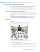
Optional Accessory Installation — Priority Page Sensor (PPS 35) Admin Building To Classroom Paging Speakers Classroom Ceiling Mounted Paging Speaker PPS 35 5 Sensor Output Priority Page Sensor (installed on Speaker Front Grille) Plenum cable N LA N LA N LA O DI ED AU IFI AM OU 3 2 1 T R L PL Extron FF 120 Flat Field Speakers T NO DOOUNDT 4/8 Ω GRSHORR OR EAKE S SP TPUT TE OU MO PV ER IR T RE -232 RS OV A IP 5S PV T OU O AU UT TP OU IN PU MI HD 3/4 LINK 1/2 LINK SIG
Installation Procedure 1. Using the hook-and-loop fastener, attach the PPS 35 to the front grille of a paging system speaker that is located within fifty feet of the PVS 405D. 2. Run the attached cable to the switcher location. 3. Connect the end of the three-wire cable to the Paging Sensor port on the rear panel of the PVS 405D. Wire the connector as shown at right. a Attach the Sensor to the front grille of a speaker 4.
Optional Accessory Installation — Priority Page Sensor Kit (PPS 25) Admin Building Classroom To Classroom Paging Speakers Ceiling Mounted Paging Speaker Priority Page Sensor FF 120 Flat Field Speakers N Sensor Output LA N LA N LA 3 2 1 T IFIE AM D AU O DI OU R L PL T NO DOOUNDT 4/8 Ω GRSHORR OR EAKE S SP TPUT E OU MOT T PV ER IR RE -232 RS OV A IP 5S PVS T O AU UT TP DI OU R TS PU HD 3/4 LINK 1/2 LINK SIG SIG WER PO V X 12 MA 3A Paging System T IN PV T IN PV MI AU
Installation Procedure WARNING: Risk of serious personal injury if installation is not done correctly. All structural steps, anchoring, and electrical installation should be performed by qualified personnel in accordance with local and national building codes, fire and safety codes, and/or local and national electrical codes. To meet the plenum rating requirement, the Priority Page Sensor assembly must be installed in a UL Listed junction box with a cover.
6. Strip 3/16 inches of insulation from each conductor on the bare wire end of the remaining blue sensor cable. Do not tin the leads. Feed the wire into the junction box (clamping it down if necessary) and connect the wires to the Page Sensor port captive screw connector (use the + and - poles) on the rear panel of the PVS 405D. Polarity need not be observed. PVS 405D Paging Sensor Port AUDIO OUT R PAGING SENSOR +V INPUT 5 PVS 405D VOICELIFT AUX R 7.
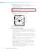
Testing and Adjustment Procedure To test that the classroom audio is muted when a PA system announcement (a page) occurs: 1. Turn the classroom audio on. 2. Speak into the PA system microphone. The classroom audio should be muted while the PA page occurs and be restored when the page ends. 3. If the program fails to mute the classroom audio during a page, turn the Sensitivity adjustment, on the front panel of the PVS 405D, clockwise. 4.
Outline of Installation Steps for WallVault Digital Systems (WMK 160) Stage 1 — Install the Screen and Projector. c Mark the screen location (page 18). c Install projector to verify location (page 18). c Verify the image location (page 21). c Cut the ceiling tile (page 22). c Preliminary safety hardware installation (page 22). c Finish projector drop ceiling mount installation (page 23). c Secure the projector drop ceiling mount to the ceiling (page 24).
Outline of Installation Steps for WallVault Digital Systems (USFM 100) Stage 1 — Install the Screen and Projector. c Mark the screen location (page 18). c Install projector to verify location (page 18). c Verify the image location (page 21). c Cut the ceiling tile (page 22). c Preliminary safety hardware installation (page 22). c Finish projector drop ceiling mount installation (page 23). c Secure the projector drop ceiling mount to the ceiling (page 24).
Outline of Installation Steps for PlenumVault Digital Systems (PVM 220) Stage 1 — Install the Screen and Projector. c Mark the screen location (page 18). c Install projector to verify location (page 18). c Verify the image location (page 21). c Cut the ceiling tile (page 22). c Preliminary safety hardware installation (page 22). c Finish projector drop ceiling mount installation (page 23). c Secure the projector drop ceiling mount to the ceiling (page 24).
Optional Accessory Installation c VoiceLift System (page 66). c Priority Page Sensor PPS 35 (page 67). c Priority Page Sensor Kit PPS 25 (page 69). The pages listed above contain instructions for installing the PlenumVault Digital System. Where possible, line drawings and photos from an actual installation are used to clarify some of the steps discussed in the text. Most images have a number corresponding to the step that is being described (for example, Ñ).
Extron Warranty Extron Electronics warrants this product against defects in materials and workmanship for a period of three years from the date of purchase.
Outline of Installation Steps for PoleVault Digital Systems Stage 1 — Install the Screen and Projector. c Mark the screen location (page 18). c Install projector to verify location (page 18). c Verify the image location (page 21). c Cut the ceiling tile (page 22). c Preliminary safety hardware installation (page 22). c Finish projector drop ceiling mount installation (page 23). c Secure the projector drop ceiling mount to the ceiling (page 24).